4. Operation
4.3 Pulse Train Control Mode
4-126
ME0342-4B
Setting T in
Parameter No. 187
Setting T in
Parameter No. 187
Setting T in
Parameter No. 187
Standby for Update of
Position Command
[7] Pulse Count Direction
No. Name Unit Input Range Default factory setting
62
Pulse count direction
−
0: Motor forward rotation
1: Motor reverse rotation
1
You can set the direction in which the motor turns according to command pulses.
[8] Select Enable/Disable Compulsory Stop Input
No. Name Unit Input Range Default factory setting
67
Select Enable/Disable
Compulsory Stop Input
− 0: Enable, 1: Disable 0
Compulsory stop of the actuator can be performed with PIO (CSTP Signal ON) from the host
system. In this parameter, a choice can be made from using (make activated) CSTP Signal
(Compulsory Stop Input Signal) and not using (make inactivated) the signal.
[9] Command Output Complete Judgment Time in Non-Positioner Mode
No. Name Unit Input Range Default factory setting
187
ms 0 to 255 0
It should be set up when a low velocity operation
(Note 1)
is to be conducted in Pulse Train Control Mode.
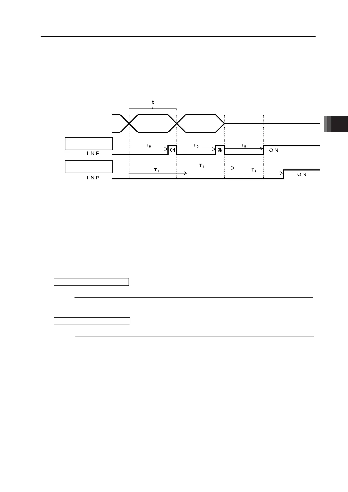
The next position command waits for a period of time set in this parameter (T in figure above) after
input of a position command from the host controller (PLC). A judgment for the positioning complete
should be made and the complete signal (INP) should be output when there is no command issued
from the host controller for a period of Time T and the deviation is in the positioning band at the
same time.
4.3 Pulse Train Control Mode
ME0342-4B 4-127
T =
T =
Therefore, if T is set shorter than the pitch (t in figure above) of sending the a position command,
judgment will be made as the positioning complete even during operation and the complete signal
(INP) should be output ((1) in figure below). At that time, the torque retaining operation at the
positioning stop will also be performed (refer to [6.1.2 [9] Current Limit at Positioning Stop]), a
smooth movement is not capable.
In the case of (1), it is necessary to set the parameter setting T
0
longer than t.
Follow the formula in the below to figure out the setting value.
[How to Figure out Setting Value]
For the lead and the encoder pulse count of each actuator, refer to [9.4.1 Specifications of
Actuators].
In the case of Linear Axis
Lead Length × Electronic Gear Numerator (Parameter No.65) × 2,000
No. of Encoder Pulses
×
Electronic Gear Denominator (Parameter No.66)
×
Minimum Velocity of Use
(Note 2)
In the case of Rotary Axis
360 × Rotary Axis Reduction Ratio × Electronic Gear Numerator (Parameter No.65) × 2,000
No. of Encoder Pulses
×
Electronic Gear Denominator (Parameter No.66)
×
Minimum Velocity of Use
(Note 2)
If the result of calculation is higher than 1, set a value rounded up.
If the result of calculation is at 1 or lower, there is no need of changing the value from the default.
Note 1 There is a need of change when a low velocity operation with the movement amount for
1ms is less than 2 pulses.
Note 2 Minimum Velocity of Use ... The lowest speed of operation
(2) When t < T
1
(1) When t > T
0

 Loading...


