6. Parameter
6.1 Parameter
6-5
ME0342-4B
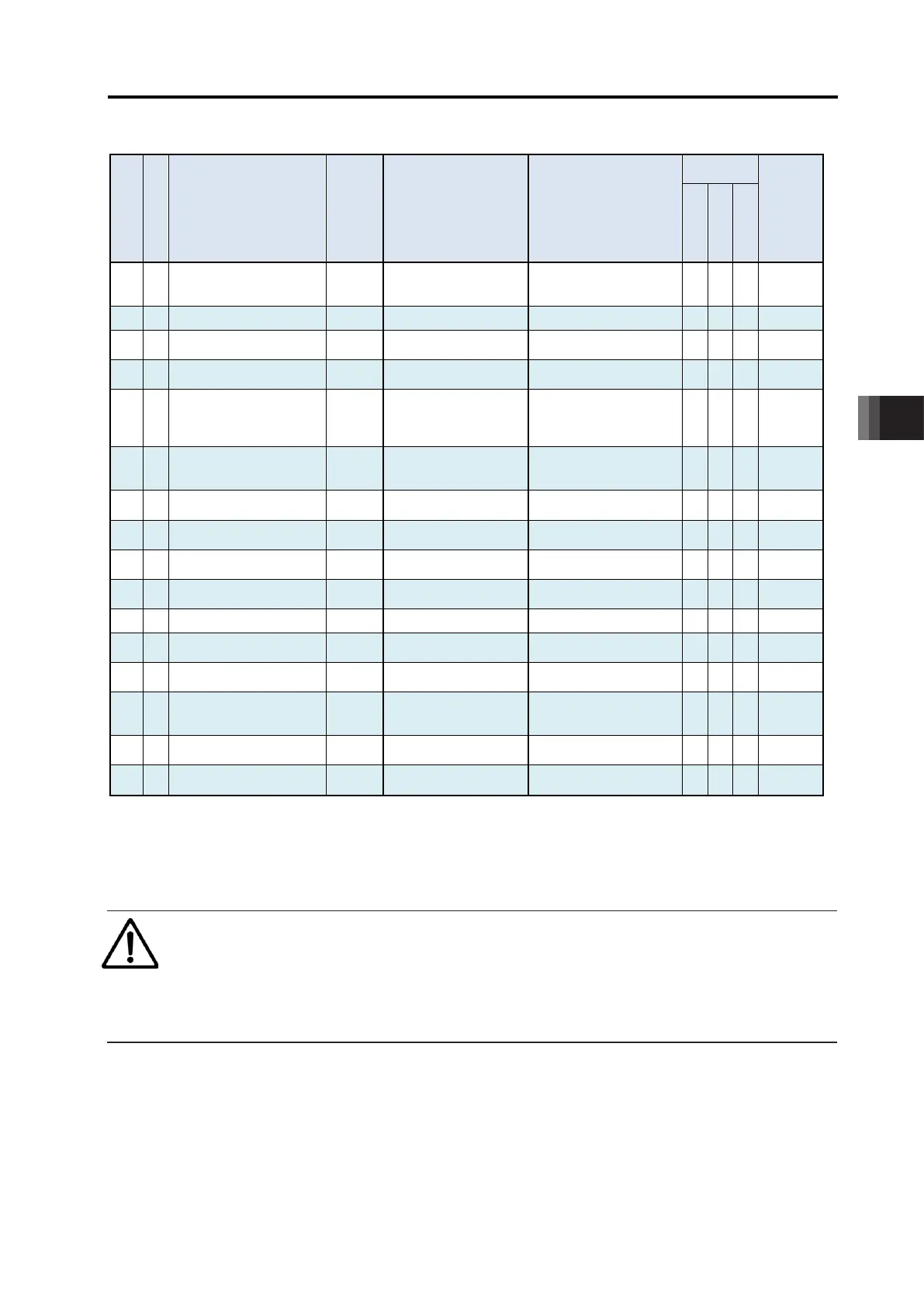
Parameter List (4/5)
No.
Name Unit
Input Range Default factory setting
Compatible
controller type
Relevant
sections
Pulse Train
90 C Fieldbus I/O format
(Note4)
- 0 to 3 Separate volume
○ - ○ 6.1.2 [67]
91 C
Current limit value at
stopping due to miss-
pressing
-
during movement
1: Current limit value
0
○ - ○ 6.1.2 [68]
92 C Select Use of Loadcell -
In accordance with actuator
(Note2)
- - ○ 6.1.2 [69]
93 C Select Pressing Control -
0: Current control
1: Force sencer
In accordance with actuator
(Note2)
Force Sensor Used
Pressing Gain
- 100 to 999,999
In accordance with actuator
(Note2)
Force Judgment Margin
Positive Side
From 1 to
Max. Pressing Force
In accordance with actuator
(Note2)
Force Judgment Margin
Negative Side
From 1 to
Max. Pressing Force
In accordance with actuator
(Note2)
- - ○ 6.1.2 [72]
110 B Stop method at servo OFF -
0: Rapid stop
1: Deceleration to stop
0
○ - ○ 6.1.2 [73]
111 B Calendar function -
1:
Use the calendar timer
1
○ ○ ○ 6.1.2 [74]
112 B Monitoring mode -
1: Monitor function 1
2: Monitor function 2
1
○ ○ ○ 6.1.2 [75]
113 B Monitoring period
ms 1 to 60,000 1
○ ○ ○ 6.1.2 [76]
117 B
Automatic Loadcell
Calibration at Startup
0: Not to Perform
1: To Perform
-
0: To Prohibit
1: To Accept
0
- - ○ 6.1.2 [78]
119 B Loadcell Calibration Time ms 1 to 9,999 10
- - ○ 6.1.2 [79]
140 B IP address
(Note4)
- 0.0.0.0 to 255.255.255.255
6.1.2 [80]
Separate volume
141 B Subnet mask
(Note4)
- 0.0.0.0 to 255.255.255.255
6.1.2 [81]
Separate volume
142 B Default gateway
(Note4)
- 0.0.0.0 to 255.255.255.255
6.1.2 [82]
Separate volume
143 B Overload level ratio % 50 to 100 100
○ - ○ 6.1.2 [83]
144 B
Gain scheduling upper limit
multiplying ratio
% 0 to 1,023 0
○ - ○ 6.1.2 [84]
145 C
GS velocity loop
proportional gain
- 1 to 99,999,999
In accordance with actuator
(Note2)
GS velocity loop integral
gain
- 1 to 99,999,999
In accordance with actuator
(Note2)
Total movement count
threshold
Times 0 to 999,999,999 0 (Disabling) ○ - ○ 6.1.2 [87]
148 B
Total operated distance
threshold
m 0 to 999,999,999 0 (Disabling) ○ ○ ○ 6.1.2 [88]
149 B Zone output changeover -
0: Not to change
1: To change
0 ○ - ○ 6.1.2 [89]
Note 2 The setting values vary in accordance with the specification of the actuator. At shipment, the parameters are set in
accordance with the specification.
Note 3 Positioner: for Positioner Mode, Pulse Train: for Pulse Train Mode, Pulse Press: for Pulse Press Train Control (PCON-CBP)
Note 4 These parameters are exclusively used for the field network type.
6.1 Parameter
ME0342-4B 6-6
Parameter List (5/5)
No.
Category
Name Unit
Input Range Default factory setting
Compatible
controller type
(Note 3)
Relevant
sections
Pulse Train
Positioner
Pulse Train
Pulse Press
151 B
Light malfunction alarm
output select
-
0:
Overload warning output
1: Message lebel alarm
1
○ ○ ○ 6.1.2 [90]
152 B High output setting - 0: Disabling, 1: Enabling
In accordance with actuator
(Note2)
○ ○ ○ 6.1.2 [91]
153 B
BU velocity loop
proportional gain
- 1 to 99,999,999
In accordance with actuator
(Note2)
○ - ○ 6.1.2 [92]
154 B
BU velocity loop integral
gain
- 1 to 99,999,999
In accordance with actuator
(Note2)
○ - ○ 6.1.2 [93]
155 A
Absolute battery retention
time
-
1: 15 days
2: 10 days
0 ○ - - 6.1.2 [94]
156 B
Torque check/Light
malfunction output select
-
0: Torque check effective
1: Light malfunction
0 ○ ○ ○ 6.1.2 [95]
159 B
FB half direct mode speed
unit
(Note 4)
-
0: Units of 1mm/s
1: Units of 0.1mm/s
Separate volume ○ - ○
6.1.2 [96]
Separate volume
165 B
Delay time after shutdown
release
ms 0 to 100 0 ○ ○ ○ 6.1.2 [97]
166 B
Startup current limit
extension feature
- 0: Disabling, 1: Enabling 0 (Disabling) ○ ○ ○ 6.1.2 [98]
167 B Pulse train datum position mm -9,999.99 to 9,999.99 0 - ○ -
168 B Collision detection feature - 0 to 7 0 ○ - ○ 6.1.2 [100]
173 B
Force Control Transition
Threshold
% 10 to 90
In accordance with actuator
(Note2)
- - ○ 6.1.2 [101]
182 B
Automatic current reduction
feature select
- 0: Disabling, 1: Enabling 0 ○ ○ ○ 6.1.2 [102]
187 C
Complete Judgement Time
ms 0 to 255 0 - ○ -
4.3.5 [9]
6.1.2 [103]
188 A Network Number
(Note4)
- 1 to 239 Separate volume ○ - ○
6.1.2 [104]
Separate volume
198 B
Select Load Monitoring
Symbol
-
0: Compression Load
1: Tension Load
0 - - ○ 6.1.2 [105]
Note 2 The setting values vary in accordance with the specification of the actuator. At shipment, the parameters are set in
accordance with the specification.
Note 3 Positioner: for Positioner Mode, Pulse Train: for Pulse Train Mode, Pulse Press: for Pulse Press Train Control (PCON-CBP)
Note 4 These parameters are exclusively used for the field network type.
Caution
● Make sure to set to “Positioner Mode” (No. 25 PIO Pattern = 0 to 5) when performing
an operation with using the serial communication.
If it happens to be in the “pulse train mode” by mistake, the controller may operate
erratically because it is operated according to the “pulse train mode” parameters.

 Loading...


