1. Controller Overview
1.3 Name for Each Parts and Their Functions
1-5
ME0342-4B
Caution
● In this manual, each type of CB/CGB is stated as CB, each type of CFB/CGFB as
CFB, and each type of CBP/CGBP as CBP.
1) Absolute Battery Connector: Refer to [3.1.3 (3)]
It is the connector to plug in the enclosed battery if applicable for Simple Absolute Type (option).
* This should not used in CFB and CBP types.
2) Absolute Battery: Refer to [2.6.2]
It is enclosed if applicable for Simple Absolute Type (option).
Use unit by affixing it on the side of PCON body with fabric hook-and-loop fastener or store it
Absolute Battery Unit (option).
* This should not used in CFB and CBP types.
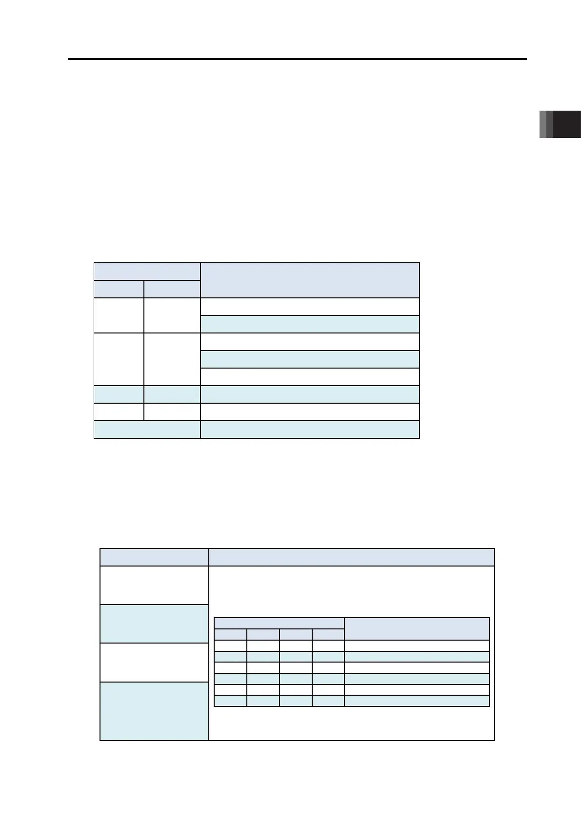
3) Absolute Battery Status Indicator LED
It is equipped if applicable for Simple Absolute Type (option).
It displays the status such as battery charge condition and error generation.
: Illuminating × : OFF
LED Operation status
1 (GN/RD) 0 (GN/OR/RD) Description
× × × Control Power OFF
(GN) (GN)
(Either color)
Absolute Reset Complete
(GN) (RD)
(Either color)
Absolute Reset Incomplete
(RD) (RD)
(Either color)
Error occurred.
(Either color)
(Either color)
(GN) Battery Fully Charged
(Either color)
(Either color)
(OR) Battery Charging Operation
(Either color)
(Either color)
(RD) Battery Disconnected
* This should not used in CFB and CBP types.
1.3 Name for Each Parts and Their Functions
ME0342-4B 1-6
4) PIO Connector/ Field Network Connector
PIO Type is equipped with the input and output signal connectors for control and Field
Network Type with connectors for each field network connection.
Refer to [3.1.2 PIO Pattern Selection and PIO Signal] or [3.2.2 I/O Signals in Pulse Train
Control Mode and Each Functions].
For details, refer to the instruction manual for each field network.
5) Controller Status Indicator LED
Following show the controller operation status:
: Illuminating × : OFF ☆ : Flashing
LED
Operation status
SV (GN) ALM (RD)
× ×
Control Power OFF
Servo OFF
×
Alarm(Operation Cancellation Level or more)
Motor Driving Power Supply OFF
In the Emergency Stop
× Servo ON
☆
× During Automatic servo-off
(Note 1)
(OR) During initialization after power is supplied
(Note 1) During automatic servo-off : Refer to [5.2.1 AUTO Servo OFF and Full Servo Function]
6) LED for Current/Alarm Monitoring
In the ordinary use, it shows the command current percentage and shows the alarm code during
an alarm being generated.
LED Operation status
STS3 (GN)
• During servo-off: it displays the current command current ratio
(proportional to the rated current).
: Illuminating × : OFF
Command Current Ratio
75.00% to 100.00% or more
• During alarm generation: it displays the simple alarm code.
Refer to [8.3.1 Simple alarm codes]
STS2 (GN)
STS1 (GN)
STS0 (GN)

 Loading...


