Intel
®
Server Chassis P4304XXMFEN2/P4304XXMUXX Product Family System Integration and Service Guide
62
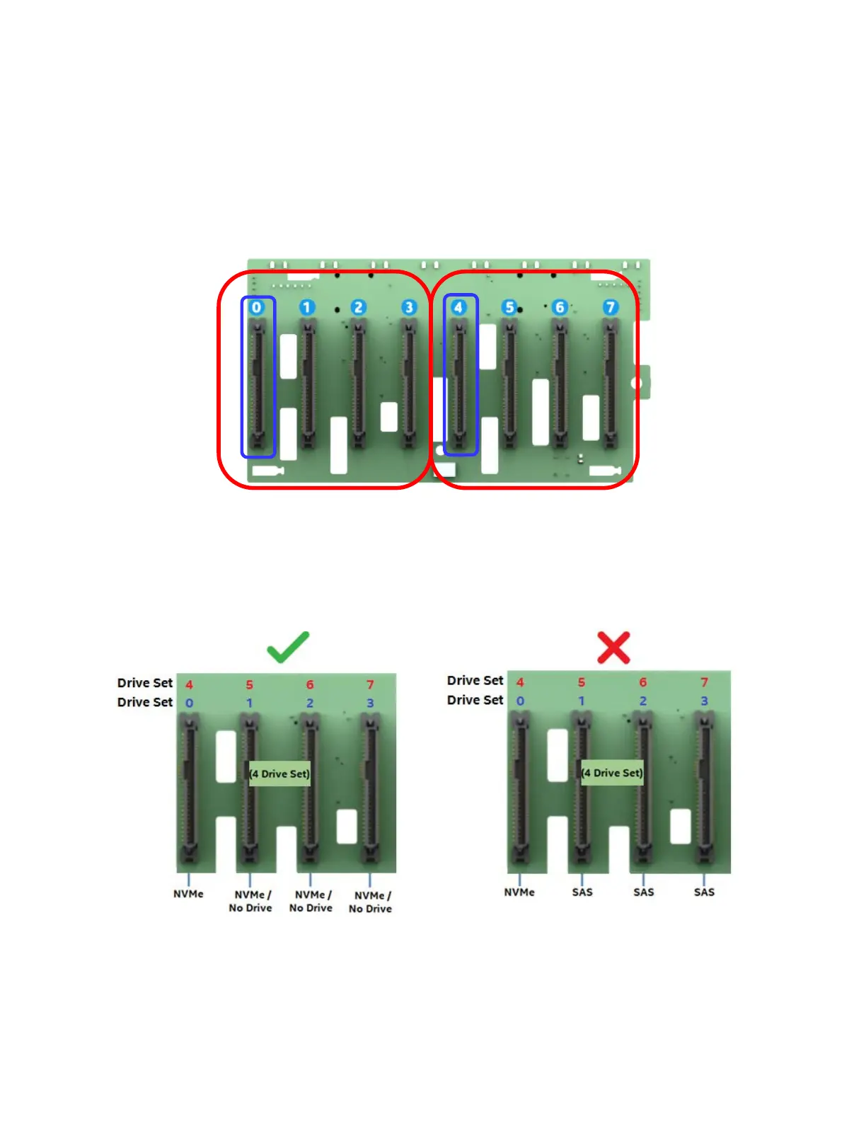
The following information is applicable when PCIe signals to the 8x2.5” combo backplane are cabled from 4
or 8 port PCIe Switch add-in cards.
• NVMe drive management sideband signals on the backplane are routed between drive connector sets:
(0,1,2,3) and (4,5,6,7)
• In order to support NVMe drive management within a defined drive set, an NVMe drive MUST be
populated in the first drive connector of the given set (drive connectors 0 or 4). Additional NVMe drives
within the drive set must be populated in sequential order with no gaps between drive connectors.
• Combining NVMe drives and SAS/SATA drives within a defined drive set is NOT supported.
The following illustrations identify supported and unsupported drive populations associated with any
defined drive set of the 8x2.5” combo backplane when an Intel® VROC key is installed to the server board
and the PCIe source to the backplane is from an add-in PCIe Switch card.
PCIe Source Drive Set
PCIe Source Drive Set
1
st
Drive = NVMe +
NVMe in any sequential
drive slot (No gaps)
Mixing of NVMe and SAS
within a common drive set
is not supported
= Supported
= Not Supported