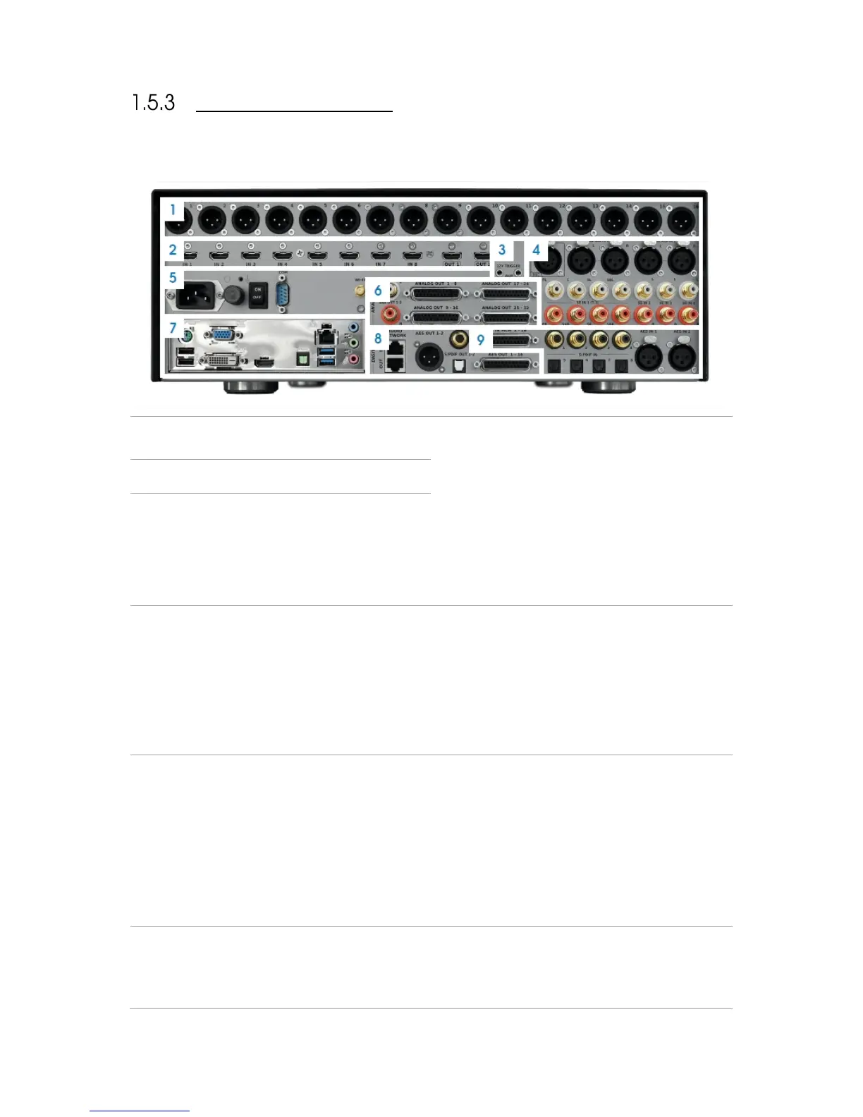
ANALOG OUTPUTS 1-16 ON XLR
CONNECTORS
PC CONNECTORS may change following PC
motherboard updates
• Video output (VGA/DVI/HDMI)
• 2x USB 2.0 + 2x USB 3.0
• Parallel port (unused)
• PS/2 Keyboard/Mouse
• RJ45 Gigabit Ethernet
• Audio ports (unused)
HDMI 1.4A 8 INPUTS, 2 OUTPUTS
ANALOG INPUTS
• 1x Microphone Input (unused)
• 2x Stereo Inputs on XLR
• 1x 7.1 Input on RCA
• 3x Stereo Inputs on RCA
DIGITAL OUTPUTS
• 1x AES3 (8 or 16 channels) on DB25
• 1x Stereo AES/EBU on XLR
• 1x Stereo S/PDIF on RCA
• 1x Stereo S/PDIF on Toslink
• 1x AML Extension link on RJ45
POWER
• AC Input
• Fuse
• Power Switch
• RS232
• Serial Number
• Wi-Fi Antenna Connector
DIGITAL INPUTS
• 1x AES3 DCI compliant (8 or 16 channels) on
DB25
• 4x SPDIF on RCA / 1x 7.1 PCM
• 4x SPDIF on Toslink / 1x 7.1 PCM
• 2x Stereo AES/EBU on XLR
ANALOG OUTPUTS
• 1-32 on 4x DB25 Connectors
• 1x Stereo on RCA


 To Next Page