To mount the switch on four posts in a rack:
1. Attach the front-mounting brackets (either the flush or the 2-in.-recess brackets) to
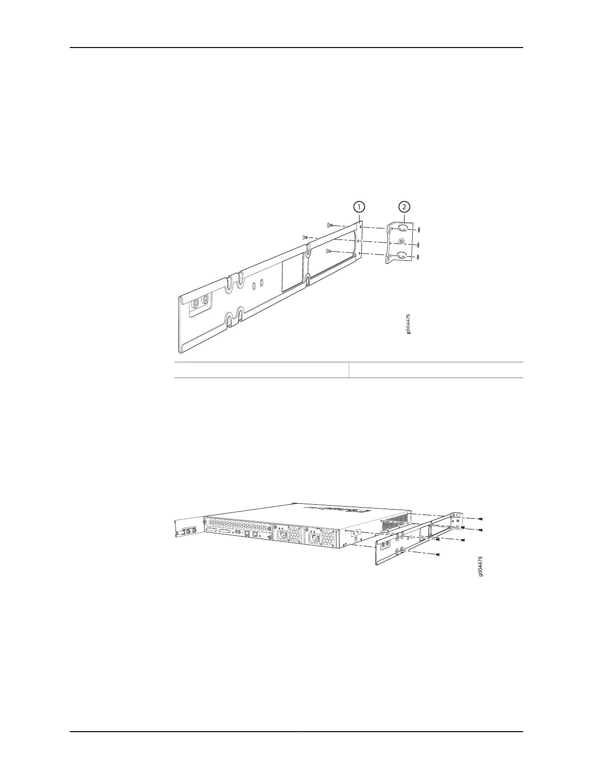
the side mounting-rails using six 4-40 flat-head Phillips mounting screws. See
Figure 27 on page 148.
Figure 27: Attaching the Front-Mounting Bracket to the Side Mounting-Rail
2—1— Front-mounting bracketSide mounting-rail
2. Place the switch on a flat, stable surface.
3. Align the side mounting-rails along the side panels of the switch chassis. Align the
two holes in the rear of the side mounting-rails with the two holes on the rear of the
side panel.
4. Insert 4x6-mm Phillips flat-head mounting screws into the two aligned holes and
tighten the screws. Ensure that the remaining four holes in the side mounting-rails are
aligned with the four holes in the side panel. See Figure 28 on page 148.
Figure 28: Attaching the Side Mounting-Rail to the Switch Chassis
5. Insert the 4x6-mm Phillips flat-head mounting screws into the remaining four holes
in the side mounting-rails and tighten the screws.
6. Have one person grasp both sides of the switch, lift the switch, and position it in the
rack, aligning the side mounting-rail holes with the threaded holes in the front post
of the rack. Align the bottom hole in both the front-mounting brackets with a hole in
each rack rail, making sure the chassis is level. See Figure 29 on page 149.
Copyright © 2016, Juniper Networks, Inc.148
EX3200 Switch Hardware Guide