• Prevention of Electrostatic Discharge Damage on page 269
• Connecting Earth Ground to an EX Series Switch on page 155
• Installing and Removing EX3200 Switch Hardware Components on page 152
LCD Panel in EX3200 Switches
The LCD panel on the front panel of the switch shows two lines of text, each of which
can contain a maximum of 16 characters. The LCD panel displays a variety of information
about the switch and also provides a menu to perform basic operations such as initial
setup and reboot.
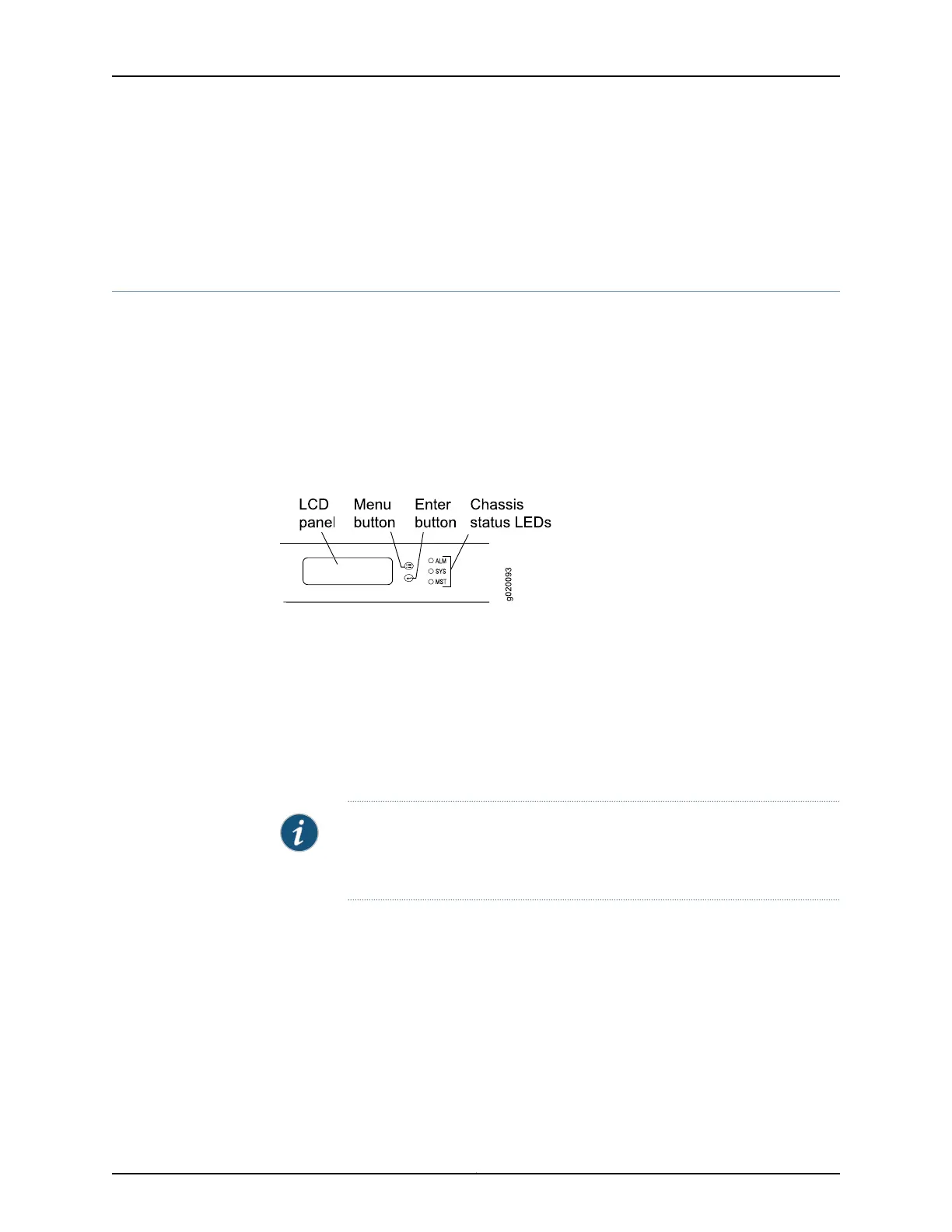
There are two navigation buttons—Menu and Enter—to the right of the LCD panel.
See Figure 4 on page 11.
Figure 4: LCD Panel
You can configure the second line of the LCD panel to display a custom message. If the
LCD panel is configured to display a custom message, the Menu button and the Enter
button are disabled. See “Configuring the LCD Panel on EX Series Switches (CLI
Procedure)” on page 183.
The LCD panel has a backlight. If the LCD panel is idle for 60 seconds, the backlight turns
off. You can turn on the backlight by pressing the Menu or Enter button once. After turning
on the backlight, you can toggle between the LCD panel menus by pressing the Menu
button and navigate through the menu options by pressing the Enter button.
NOTE: The chassis viewer in the J-Web interfacealso displays the LCD panel.
From the J-Web interface, you can view real-time status information in the
LCD panel. See “Dashboard for EX Series Switches” on page 35.
This topic describes:
•
LCD Panel Modes on page 11
•
LCD Panel Menus on page 12
LCD Panel Modes
The LCD panel operates in four modes: boot, idle, status, and maintenance.
The LCD panel operates in boot mode during switch reboot. The boot mode displays the
key milestones in the switch boot process. The boot mode does not have any menu
11Copyright © 2016, Juniper Networks, Inc.
Chapter 2: Chassis Components and Descriptions