EasyManuals Logo

Juniper EX3200 Hardware Guide

Juniper EX3200
310 pages
To Next Page IconTo Next Page
To Previous Page IconTo Previous Page
Page #49 background imageLoading...
Page #49 background image
CHAPTER 3
Cooling System and Airflow
Cooling System and Airflow in an EX3200 Switch on page 27
Cooling System and Airflow in an EX3200 Switch
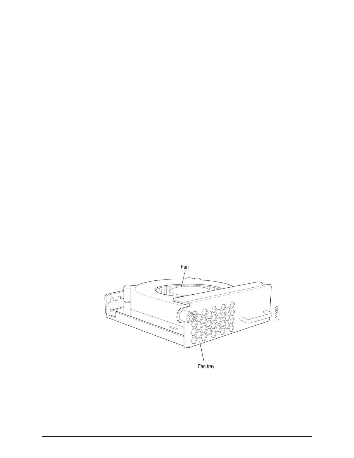
The cooling system in an EX3200 switch consists of a field-replaceable unit (FRU) fan
tray with one fan (see Figure 14 on page 27).
This topic describes:
Fan Tray on page 27
Airflow Direction in the EX3200 Switch Chassis on page 27
Fan Tray
The fan tray is located at the rear of the chassis. See Figure 14 on page 27
Figure 14: Fan Tray Used in an EX3200 Switch
Airflow Direction in the EX3200 Switch Chassis
The fan tray located at the rear of the chassis provides side-to-rear chassis cooling. See
Figure 15 on page 28
27Copyright © 2016, Juniper Networks, Inc.

Table of Contents

Other manuals for Juniper EX3200

Questions and Answers:

Question and Answer IconNeed help?

Do you have a question about the Juniper EX3200 and is the answer not in the manual?

Juniper EX3200 Specifications

General IconGeneral
ModelEX3200
Rack Units1U
Layer SupportLayer 2 and Layer 3
Junos OSYes
Maximum VLANs4093
DRAM512 MB
Flash Memory256 MB
Ports24 or 48
Uplink Ports4 SFP
Power SupplyAC or DC
MAC Address Table Size16, 000 entries
Dimensions (W x D x H)17.4 x 14.4 x 1.7 inches
Weight12.3 lb (5.6 kg)
Operating Temperature0°C to 40°C
Operating Humidity10% to 85% (non-condensing)

Related product manuals