If the mounting screws are inserted in wall board with no stud behind it, you must use
dry wall anchors rated to support 75 lb (34 kg). Insert the screws into wall studs
wherever possible to provide added support for the chassis.
Screw the screws only part way in, leaving about 1/4 in. (6 mm) distance between
the head of the screw and the wall.
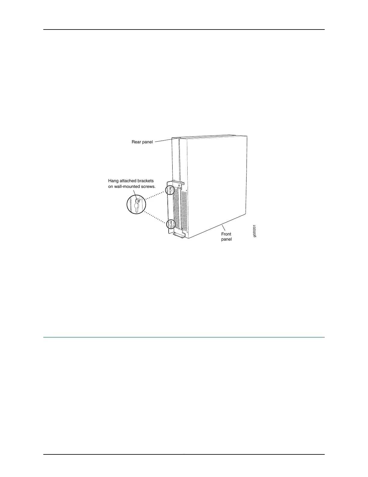
4. Grasp each side of the switch or switches, lift the switch or switches, and hang the
brackets from the mounting screws as shown in Figure 32 on page 152.
Figure 32: Mounting the Switch on a Wall
Hang attached brackets
on wall-mounted screws.
g020201
Front
panel
Rear panel
5. Tighten the mounting screws.
Related
Documentation
Connecting AC Power to an EX3200 Switch on page 161•
• Connecting DC Power to an EX3200 Switch on page 163
• Connecting and Configuring an EX Series Switch (CLI Procedure) on page 175
• Connecting and Configuring an EX Series Switch (J-Web Procedure) on page 178
• Wall-Mounting Warning for EX3200 Switches on page 252
Installing and Removing EX3200 Switch Hardware Components
The EX3200 switch chassis is a rigid sheet-metal structure that houses the hardware
components. The field-replaceable units (FRUs) in EX3200 switches are:
•
Power supply
•
Fan tray
•
Uplink module
•
SFP transceiver
•
SFP+ transceiver
•
XFP transceiver
Copyright © 2016, Juniper Networks, Inc.152
EX3200 Switch Hardware Guide