a. Remove the jumpers on the power supply terminal block.
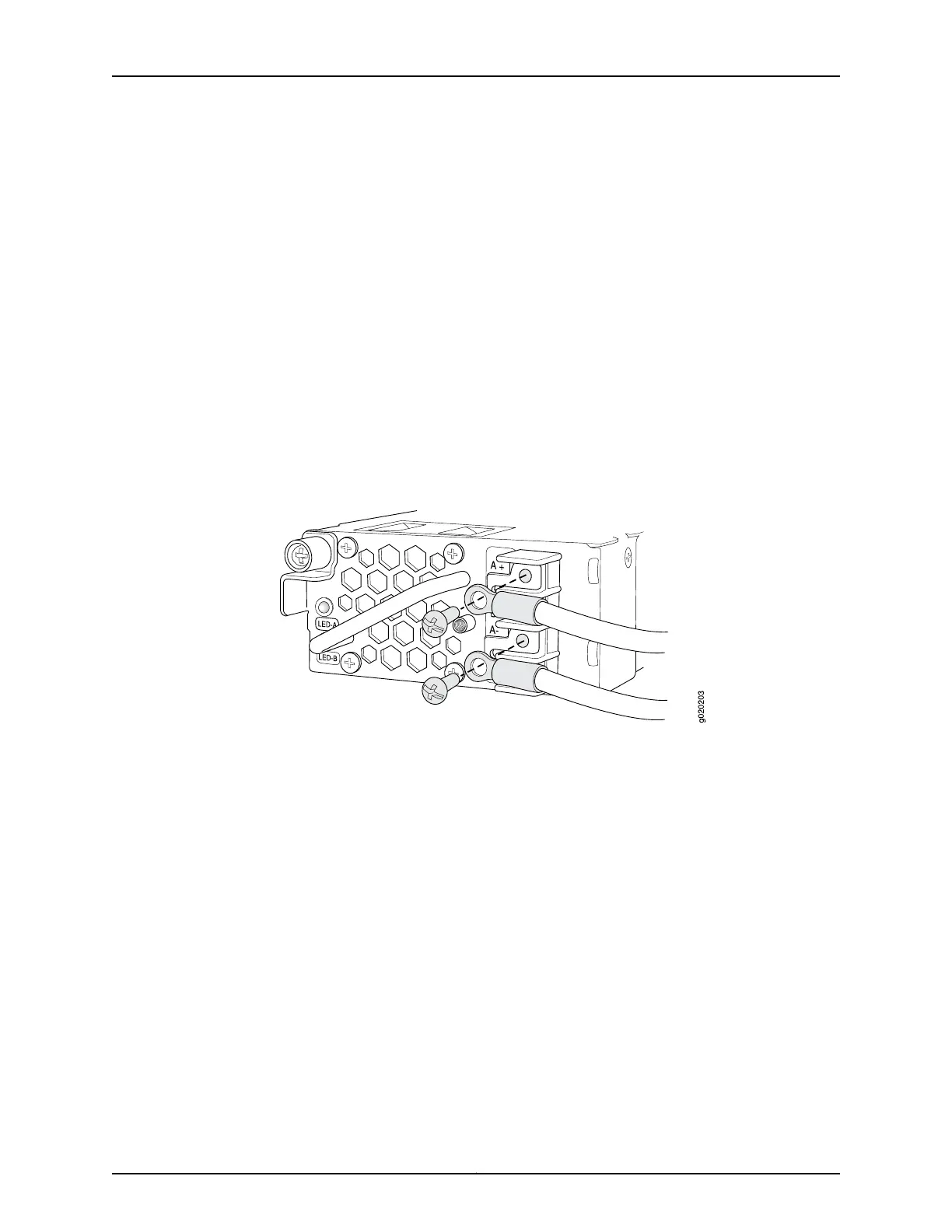
b. Secure the ring lug of the positive (+) DC power source cable from the first DC
power source to the A+ terminal on the first DC power supply.
c. Secure the ring lug of the negative (–) DC power source cable from the first DC
power source to the A– terminal on the first DC power supply.
d. Secure the ring lug of the positive (+) DC power source cable from the second
DC power source to the A+ terminal on the second DC power supply.
e. Secure the ring lug of the negative (–) DC power source cable from the second
DC power source to the A– terminal on the second DC power supply.
f. Tighten the screws on the power supply terminals on both the power supplies
until snug using the screwdriver. Do not overtighten—apply between 8 lb-in.
(0.9 Nm) and 9 lb-in. (1.02 Nm) of torque to the screws.
Figure 39: Securing Ring Lugs to the Terminals on the DC Power Supply
6. Replace the terminal block cover and secure it using the screw. Use the screwdriver
to tighten the screw.
7. Close the input circuit breaker.
8. Verify that the LEDs on the power supply are lit green and are on steadily.
Related
Documentation
• Connecting and Configuring an EX Series Switch (CLI Procedure) on page 175
• Connecting and Configuring an EX Series Switch (J-Web Procedure) on page 178
• Power Supply in EX3200 Switches on page 29
• DC Power Supply LEDs in EX3200 Switches on page 33
Copyright © 2016, Juniper Networks, Inc.166
EX3200 Switch Hardware Guide