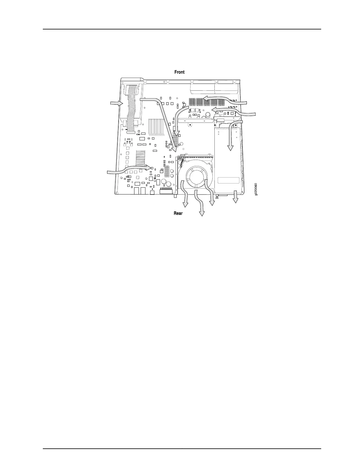
Figure 20: Airflow Through the EX3200 Switch Chassis
•
Allow at least 6 in. (15.2 cm) of clearance on the side between devices that have fans
or blowers installed. Allow 2.8 in. (7 cm) between the side of the chassis and any
non-heat-producing surface such as a wall.
•
If you are mounting the switch on a rack or cabinet with other equipment, or if you are
placing it on the desktop or floor near other equipment, ensure that the exhaust from
other equipment does not blow into the intake vents of the chassis.
•
Leave at least 24 in. (61 cm) both in front of and behind the switch. For service personnel
to remove and install hardware components, you must leave adequate space at the
front and back of the switch. NEBS GR-63 recommends at least 30 in. (76.2 cm) in
front of the rack or cabinet and 24 in. (61 cm) behind the rack or cabinet.
Related
Documentation
• Rack Requirements on page 64
• Cabinet Requirements on page 65
• General Site Guidelines on page 62
• Rack-Mounting and Cabinet-Mounting Warnings on page 248
• Cooling System and Airflow in an EX3200 Switch on page 27
67Copyright © 2016, Juniper Networks, Inc.
Chapter 6: Preparation Overview