Related
Documentation
See Rear Panel of an EX3200 Switch on page 10 for port location.•
• Connecting a Device to a Network for Out-of-Band Management on page 167
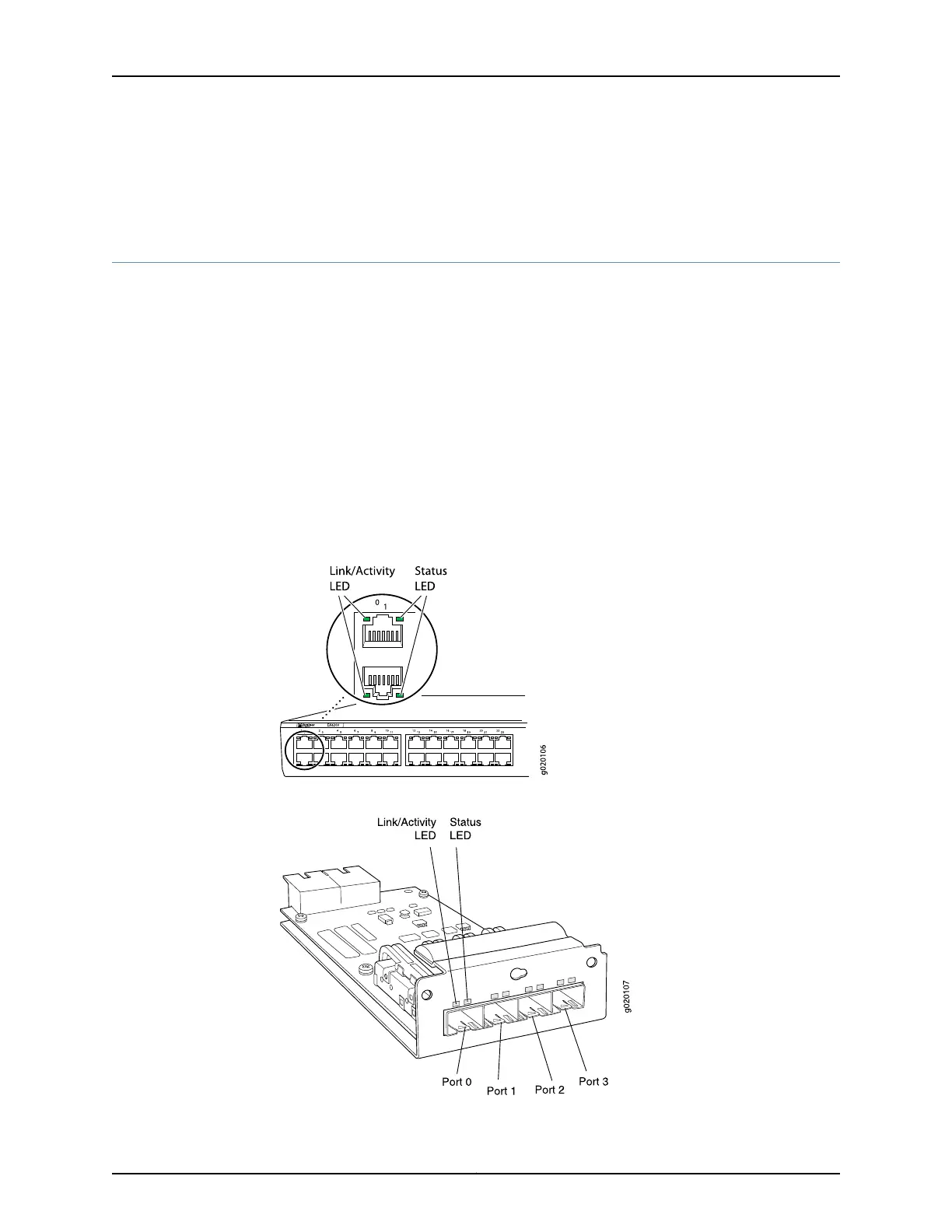
Network Port LEDs in EX3200 Switches
Each network port on the switch has two LEDs. The four figures in this topic show the
location of those LEDs:
•
Figure 10 on page 21 shows the location of the LEDs on the network ports on the front
panel.
•
Figure 11 on page 21 shows the location of the LEDs on the uplink module ports on the
SFP uplink module.
•
Figure 12 on page 22 shows the location of the LEDs on the uplink module ports on the
SFP+ and SFP+ MACsec uplink modules.
•
Figure 13 on page 22 shows the location of the LEDs on the uplink module ports on the
XFP uplink module.
Figure 10: LEDs on the Network Ports on the Front Panel
Figure 11: LEDs on the Uplink Module Ports on the SFP Uplink Module
21Copyright © 2016, Juniper Networks, Inc.
Chapter 2: Chassis Components and Descriptions