NOTE: The A+ and B+ terminals are referred to as +RTN and A– and B–
terminals arereferred to as–48 Vin “DC PowerWiringSequence Warning”
on page 277 and “DC Power Electrical Safety Guidelines for Switches” on
page 272.
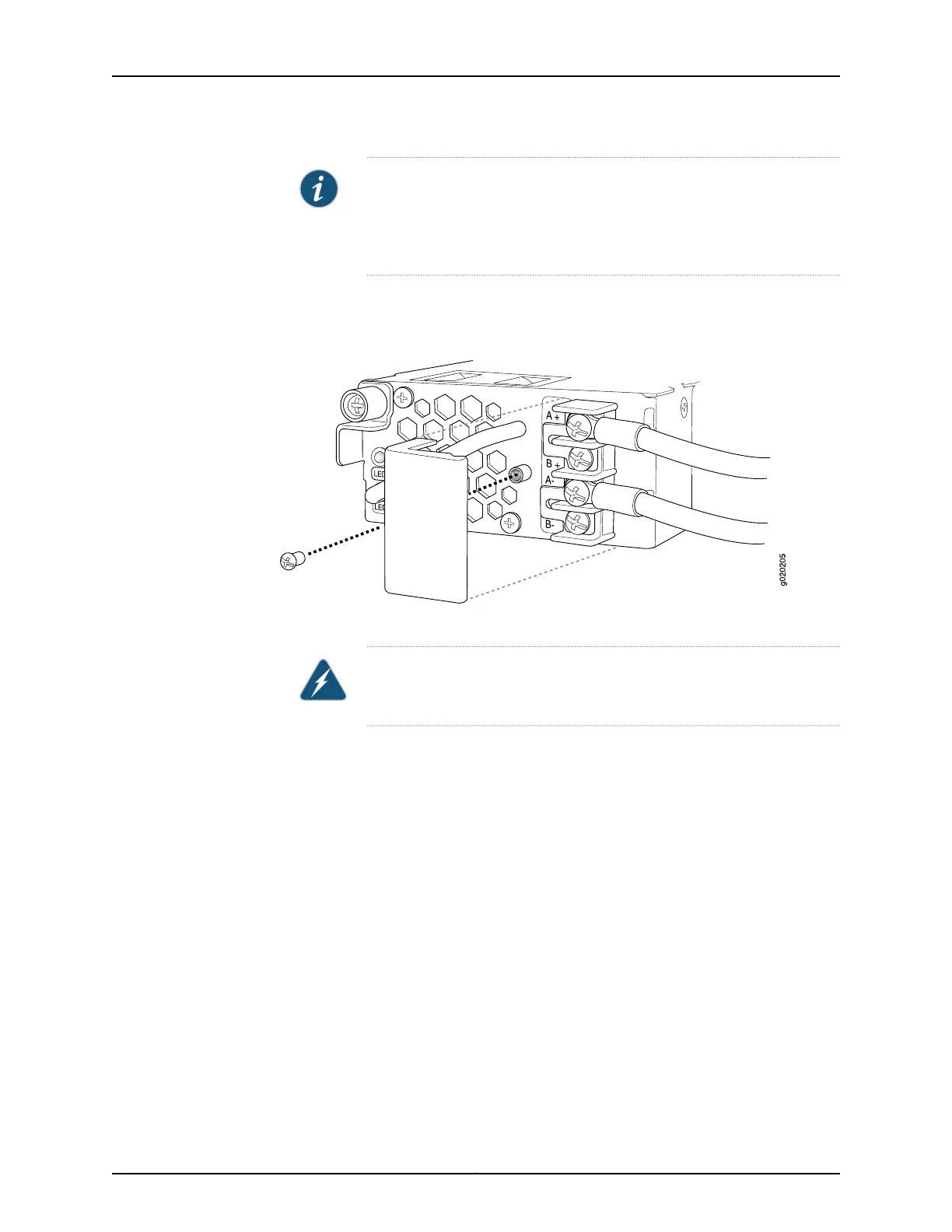
3. Removethe screw securing the terminal block cover using the screwdriver and remove
the terminal block cover (see Figure 38 on page 165). Save the screw.
Figure 38: Removing the Terminal Block Cover from a DC Power Supply
4. Remove the screws on the terminals using the screwdriver. Save the screws.
WARNING: Ensure that the power cables do not block access to switch
components or drape where people can trip on them.
5. Connect the power supplies to the power sources. Secure power source cables to the
power supplies by screwing the ring lugs attached to the cables to the appropriate
terminals by using the screw from the terminals (see Figure 39 on page 166).
•
To connect a power supply to a power source:
a. Leave the jumpers on the power supply terminals in place.
b. Secure the ring lug of the positive (+) DC power source cable to the A+ or B+
terminal on the DC power supply.
c. Secure the ring lug of the negative (–) DC power source cable to the A– or B–
terminal on the DC power supply.
d. Tighten the screws on the power supply terminals until snug using the screwdriver.
Do not overtighten—apply between 8 lb-in. (0.9 Nm) and 9 lb-in. (1.02 Nm) of
torque to the screws.
If you have a second installed power supply, connect it in the same way you did the
first.
•
To connect one power supply to two power sources:
165Copyright © 2016, Juniper Networks, Inc.
Chapter 12: Connecting the Switch to Power