• Installing an Uplink Module in an EX3200 Switch on page 195
• Removing an Uplink Module from an EX3200 Switch on page 197
• Installing a Transceiver on page 201
• Removing a Transceiver on page 203
Front Panel of an EX3200 Switch
The front panel of an EX3200 switch consists of the following components:
•
10/100/1000Base-T Gigabit Ethernet ports, some orall of which areenabled for Power
over Ethernet (PoE)
•
Uplink module ports—SFP, SFP+, or XFP ports (Installing the uplink module is an
optional feature.)
•
LCD panel and the LCD navigation buttons
•
Chassis status LEDs
•
Network port LEDs
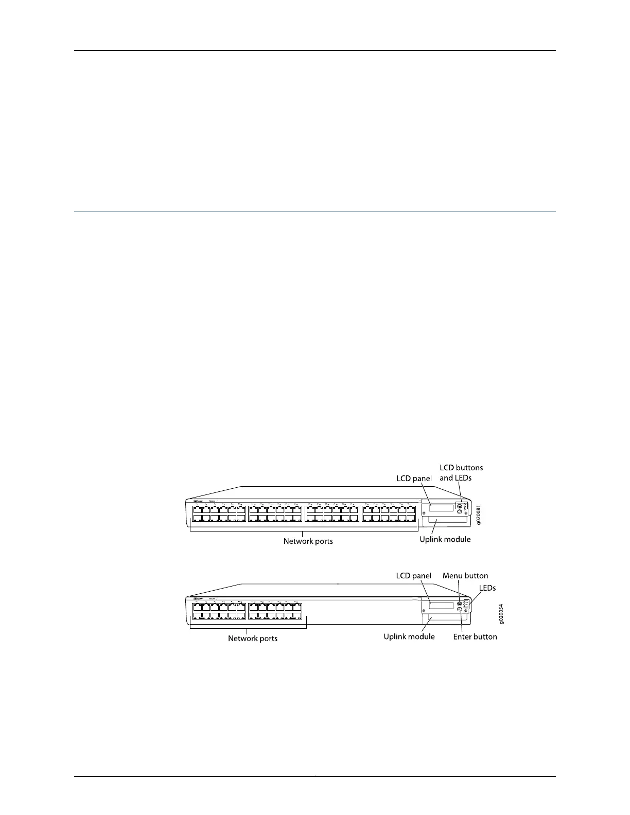
Figure 1 on page 9 shows the front panel of an EX3200 switch with 48 Gigabit Ethernet
ports. Figure 2 on page 9 shows the front panel of an EX3200 switch with 24 Gigabit
Ethernet ports. Models are available that have either all ports equipped for Power over
Ethernet (PoE) or only 8 ports equipped for PoE. All ports have 10/100/1000Base-T
Gigabit Ethernet connectors.
Figure 1: EX3200 Switch with 48 Gigabit Ethernet Ports
Figure 2: EX3200 Switch with 24 Gigabit Ethernet Ports
Related
Documentation
Chassis Status LEDs in EX3200 Switches on page 18•
• Rear Panel of an EX3200 Switch on page 10
• Network Port LEDs in EX3200 Switches on page 21
• Network Port Connector Pinout Information for an EX3200 Switch
9Copyright © 2016, Juniper Networks, Inc.
Chapter 2: Chassis Components and Descriptions