• LCD Panel in EX3200 Switches on page 11
• Installing and Removing EX3200 Switch Hardware Components on page 152
• Installing an Uplink Module in an EX3200 Switch on page 195
• Removing an Uplink Module from an EX3200 Switch on page 197
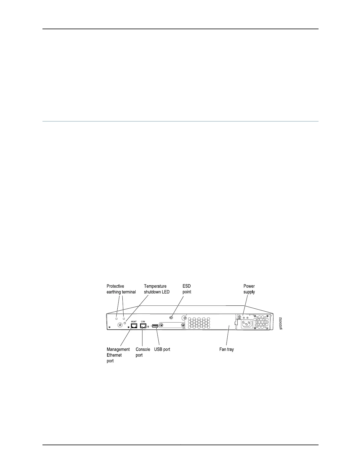
Rear Panel of an EX3200 Switch
The rear panel of the EX3200 switch consists of the following components:
•
Protective earthing terminal
•
Temperature shutdown LED
•
Management Ethernet port
•
Console port
•
USB port
•
ESD point
•
Fan tray
•
Power supply
Figure 3 on page 10 shows the rear panel of an EX3200 switch with a 320 W power
supply. All EX3200 switches have the same rear panel. The 320 W AC power supply and
the 190 W DC power supply are flush with the chassis. The 600 W AC power supply and
930 W AC power supply extend out of the chassis by 2.25 in. The power cord retainer
clips extend out of the power supply by 3 in.
Figure 3: EX3200 Switch Rear Panel
Related
Documentation
Field-Replaceable Units in EX3200 Switches on page 8•
• Front Panel of an EX3200 Switch on page 9
• USB Port Specifications for an EX Series Switch on page 120
• Cooling System and Airflow in an EX3200 Switch on page 27
• Power Supply in EX3200 Switches on page 29
Copyright © 2016, Juniper Networks, Inc.10
EX3200 Switch Hardware Guide