If the operating mode and the configured mode for the uplink module are different, it is
shown in the output of show chassis pic fpc-slot slot number pic-slot 1.
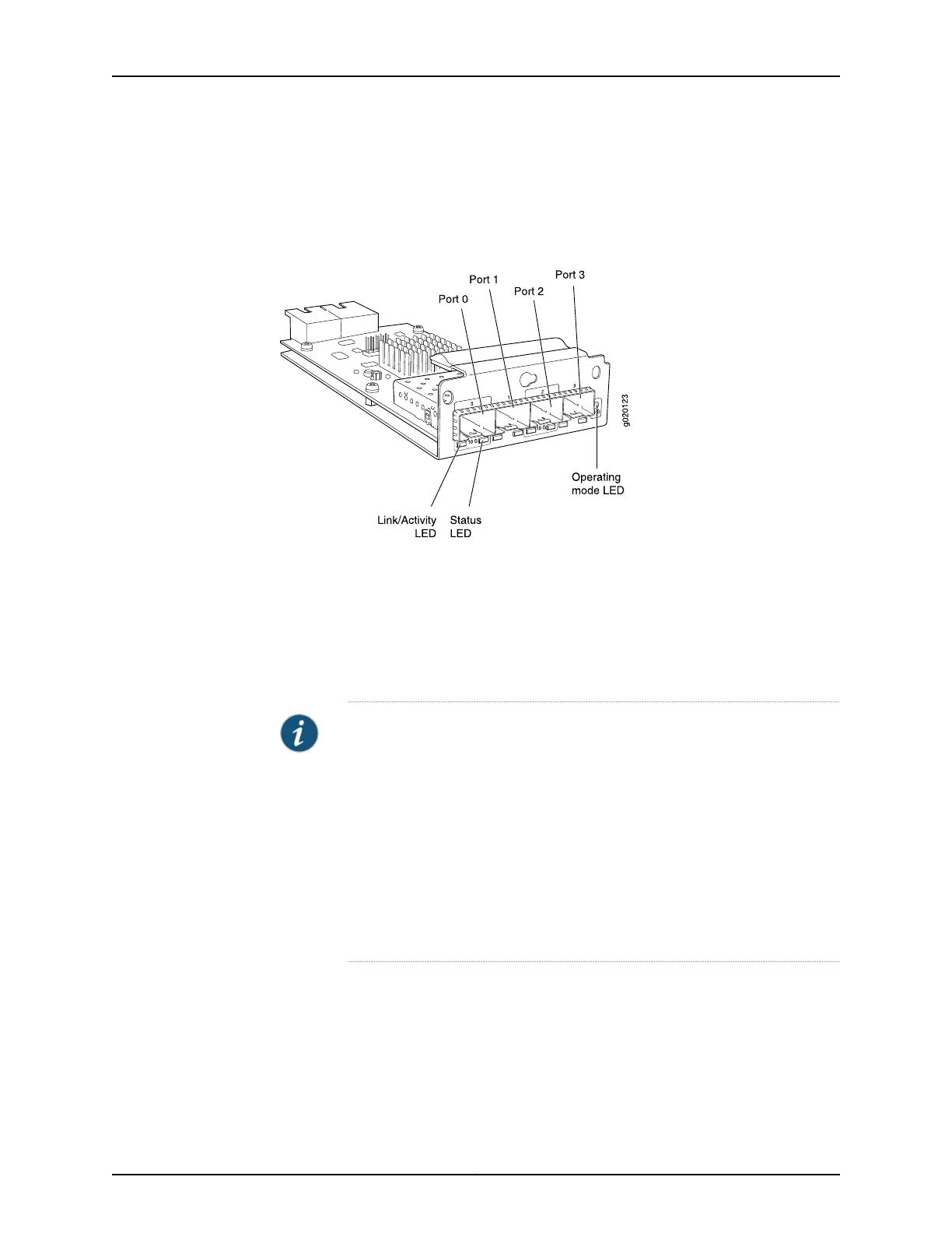
Figure 6 on page 17 shows the SFP+ uplink module and the SFP+ MACsec uplink module.
Figure 6: SFP+ and SFP+ MACsec Uplink Module
The following transceivers can be installed in the uplink module ports:
•
SFP+ transceivers are supported in ports 0 and 2.
•
SFP transceivers are supported in all four ports.
The ports that support SFP+ transceivers are labeled 10 G on the uplink module’s
faceplate (see Figure 6 on page 17).
NOTE: When an SFP+ uplink module or an SFP+ MACsec uplink module is
operating in 10-gigabit mode:
•
Only the 10-gigabit ports (ports 0 and 2) are enabled.
•
You can use only SFP+ transceivers in those ports.
When an SFP+ uplink module or an SFP+ MACsec uplink module is operating
in 1-gigabit mode:
•
All four ports are enabled.
•
You can use only SFP transceivers in all four ports.
The SFP+ uplink module and the SFP+ MACsec uplink module have an LED on the
faceplate (labeled Operating mode LED in Figure 6 on page 17) that indicates the
operating mode. If the uplink module is operating in the 10-gigabit mode, the LED is lit.
If the uplink module is operating in the 1-gigabit mode, the LED is unlit.
SFP+ uplink modules and the SFP+ MACsec uplink modules are shipped with dust covers
preinstalled in the ports.
17Copyright © 2016, Juniper Networks, Inc.
Chapter 2: Chassis Components and Descriptions