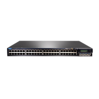
Table 30: Chassis Viewer for XRE200 External Routing Engines (continued)
DescriptionField
In the image, the colors listed below denote the interface
status:
•
Green—Interface is up and operational.
•
Yellow—Interface is up but is nonoperational.
•
Gray—Interface is down and nonoperational.
Mouse over the interface (port) to view more information.
For a Virtual Chassis configuration, select the switch to view
the interface status.
Interface status
The console port is used to connect the switch to a
management host such as a PC or a laptop.
Console port
The management port is used to connect the switch to a
management device for out-of-band management. Use this
port for initial switch configuration.
Management (me0) port
In the image, the colors listed below denote the VCP status:
•
Green—VCP is up and operational.
•
Yellow—VCP is up but is nonoperational.
•
Gray—VCP is down and nonoperational.
Mouse over the interface (port) to view more information.
Virtual Chassis port
LCD panel configured for the LEDs on the ports. Mouse over
the icon to view the current character display.
LCD panel
The active slots contain a gray temperature icon. Mouse over
the icon to display temperature information for the slot.
Temperature
Indicates the USB port for the switch.
NOTE: We recommend that you use USB flash drives
purchased from Juniper Networks for your EX Series switch.
USB port
You can install a Virtual Chassis module in the PIC1 slot. Mouse
over the Virtual Chassis ports to display the port status details.
PIC1 slot
You can install a Virtual Chassis module in the PIC2 slot. Mouse
over the Virtual Chassis ports to display the port status details.
PIC2 slot
Rear View of the XRE200 External Routing Engine
Mouse over the fan modules to display the status of the fans
and airflow direction information. For a Virtual Chassis, the
status of the fans of the selected member switch is displayed.
Fan modules
Mouse over the power supply icons to display name, status,
and description information.
Power supplies
53Copyright © 2016, Juniper Networks, Inc.
Chapter 5: Viewing System Information

 Loading...