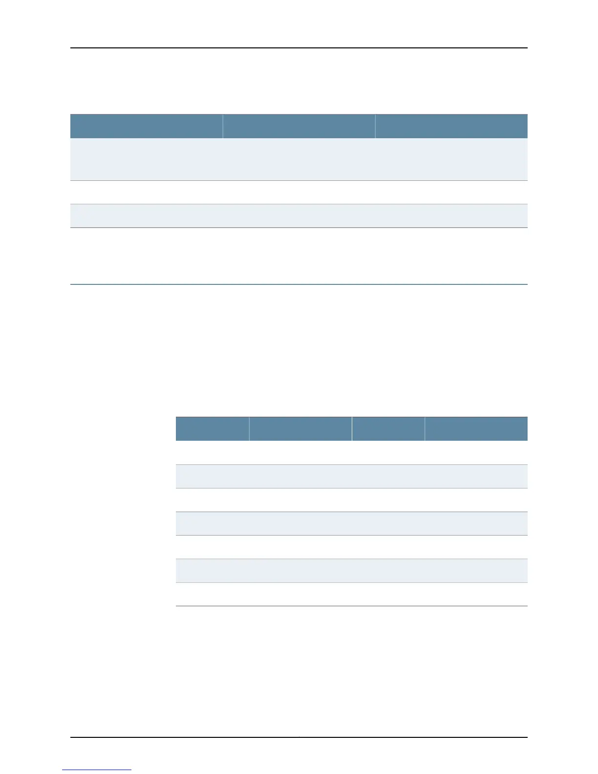
Table 47: Network Port Connector Pinout Information (continued)
DescriptionSignalPin
Transmit/receive data pair 2
Positive Vport (in PoE models)
TRP2-6
Transmit/receive data pair 4TRP4+7
Transmit/receive data pair 4TRP4-8
Related
Documentation
Front Panel of an EX4200 Switch on page 11•
RJ-45 to DB-9 Serial Port Adapter Pinout Information for a Switch
The console port is an RS-232 serial interface that uses an RJ-45 connector to connect
to a management device such as a PC or a laptop. If your laptop or PC does not have a
DB-9 male connector pin and you want to connect your laptop or PC to the switch, use
a combination of the RJ-45 to DB-9 female adapter supplied with the switch along with
a USB to DB-9 male adapter.
Table 48 on page 129 provides the pinout information for the RJ-45 to DB-9 serial port
adapter.
Table 48: RJ-45 to DB-9 Serial Port Adapter Pinout Information
SignalDB-9 PinSignalRJ-45 Pin
CTS8RTS1
DSR6DTR2
RXD2TXD3
GND5GND4
TXD3RXD6
DTR4DSR7
RTS7CTS8
Related
Documentation
Connecting a Switch to a Management Console on page 187•
• Connecting and Configuring an EX Series Switch (CLI Procedure) on page 195
• Connecting an EX9200 Switch to a Management Console or an Auxiliary Device
• Connecting and Configuring an EX9200 Switch (CLI Procedure)
• Connecting and Configuring an OCX1100 Switch (CLI Procedure)
129Copyright © 2015, Juniper Networks, Inc.
Chapter 9: Pinout Specifications