EasyManuals Logo

Juniper EX4200 User Manual

Juniper EX4200
344 pages
To Next Page IconTo Next Page
To Previous Page IconTo Previous Page
Page #94 background imageLoading...
Page #94 background image
Clearance Requirements for Airflow and Hardware Maintenance for EX4200 Switches
When planning the site for installing an EX4200 switch, you must allow sufficient
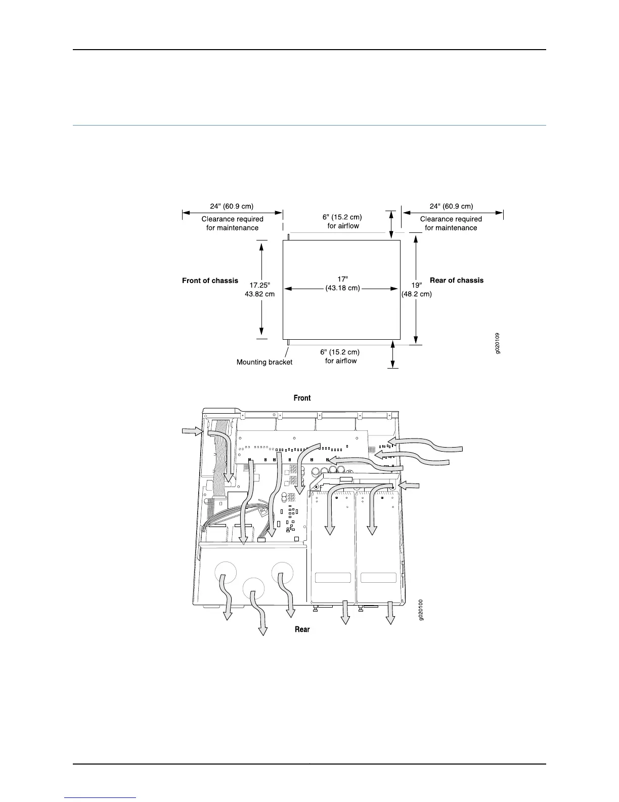
clearance around the installed switch (see Figure 20 on page 72).
Figure 20: Clearance Requirements for Airflow and Hardware Maintenance
for EX4200 Switches
Figure 21: Airflow Through the EX4200 Switch Chassis
Allow at least 6 in. (15.2 cm) of clearance on the side between devices that have fans
or blowers installed. Allow 2.8 in. (7 cm) between the side of the chassis and any
non-heat-producing surface such as a wall.
Copyright © 2015, Juniper Networks, Inc.72
EX4200 Switch Hardware Guide

Table of Contents

Other manuals for Juniper EX4200

Questions and Answers:

Question and Answer IconNeed help?

Do you have a question about the Juniper EX4200 and is the answer not in the manual?

Juniper EX4200 Specifications

General IconGeneral
ModelEX4200
Switching Capacity128 Gbps
LayerLayer 2 and Layer 3
Form Factor1U
Throughput96 Mpps
Maximum VLANs4096
MAC Address Table Size16, 000
DRAM1 GB
Flash Memory1 GB
Forwarding Rate96 Mpps
JUNOS SoftwareYes
Ports24 or 48
StackingUp to 10 switches in a Virtual Chassis configuration
Power SupplyAC or DC
ManagementCLI, SNMP, J-Web
Input Voltage100-240 VAC or -48 VDC
Operating Temperature0°C to 45°C
RedundancyRedundant power supplies
Virtual Chassis TechnologyYes
Storage Temperature-40°C to 70°C
Humidity5% to 90% non-condensing

Related product manuals