•
Screws to secure the chassis and the rear mounting-blades to the rack (not provided)
•
Dust covers for ports (for EX4200-24F switches only; optional)
NOTE: One person must be available to lift the switch while another secures
it to the rack.
CAUTION: If you are mounting multiple units on a rack, mount the heaviest
unit at the bottom of the rack and mount the other units from the bottom of
the rack to the top in decreasing order of the weight of the units.
To mount the switch on four posts in a rack:
1. Attach the front-mounting brackets (either the flush or the 2-in.-recess brackets) to
the side mounting-rails using six 4-40 flat-head Phillips mounting screws. See
Figure 33 on page 164.
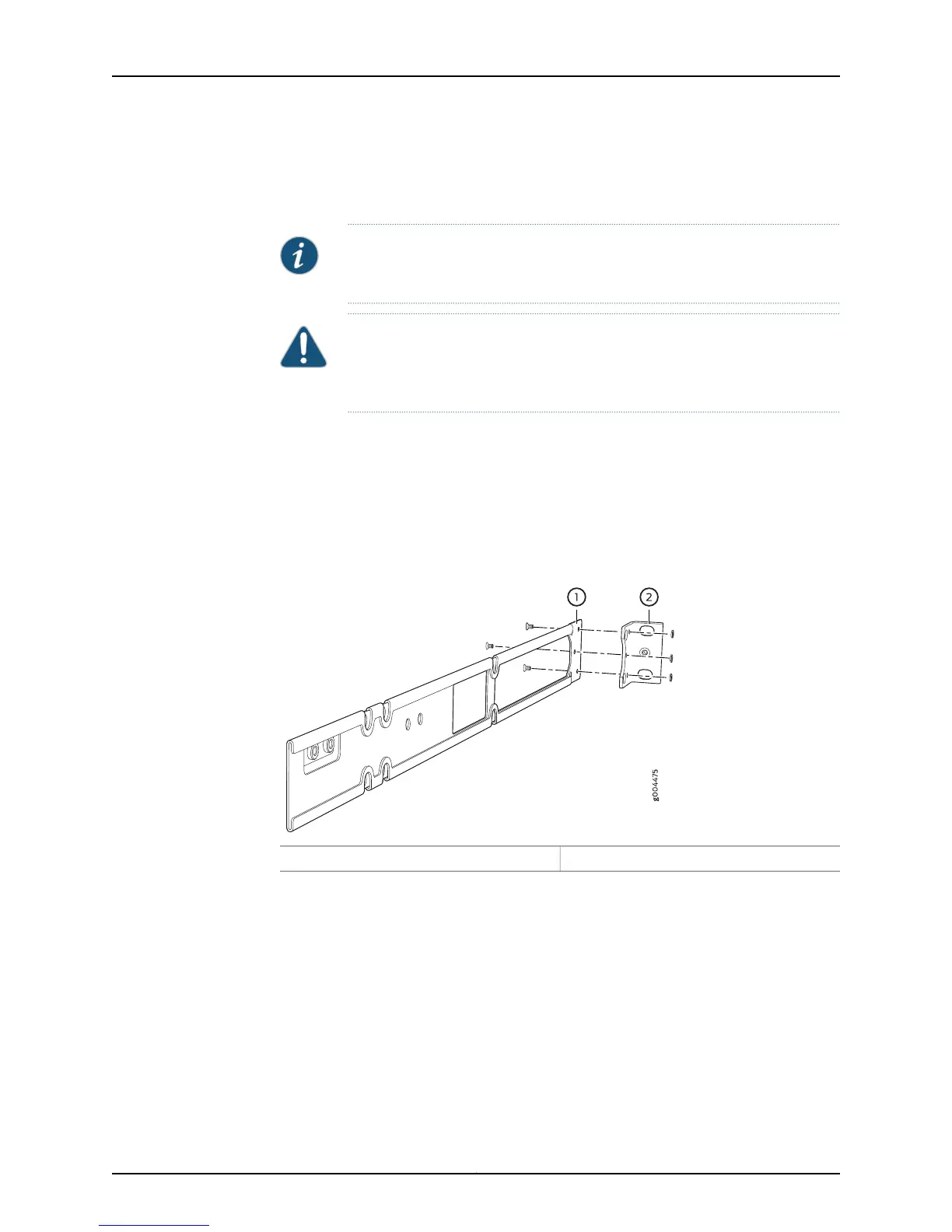
Figure 33: Attaching the Front-Mounting Bracket to the Side Mounting-Rail
2—1— Front-mounting bracketSide mounting-rail
2. Place the switch on a flat, stable surface.
3. Align the side mounting-rails along the side panels of the switch chassis. Align the
two holes in the rear of the side mounting-rails with the two holes on the rear of the
side panel.
4. Insert 4x6-mm Phillips flat-head mounting screws into the two aligned holes and
tighten the screws. Ensure that the remaining four holes in the side mounting-rails are
aligned with the four holes in the side panel. See Figure 34 on page 165.
Copyright © 2015, Juniper Networks, Inc.164
EX4200 Switch Hardware Guide