EasyManuals Logo

Juniper EX4200 User Manual

Juniper EX4200
344 pages
To Next Page IconTo Next Page
To Previous Page IconTo Previous Page
Page #152 background imageLoading...
Page #152 background image
Uplink Modules Connector Pinout Information for EX4200 Switches
EX4200 switches have a field-replaceable unit (FRU) uplink module on the front panel.
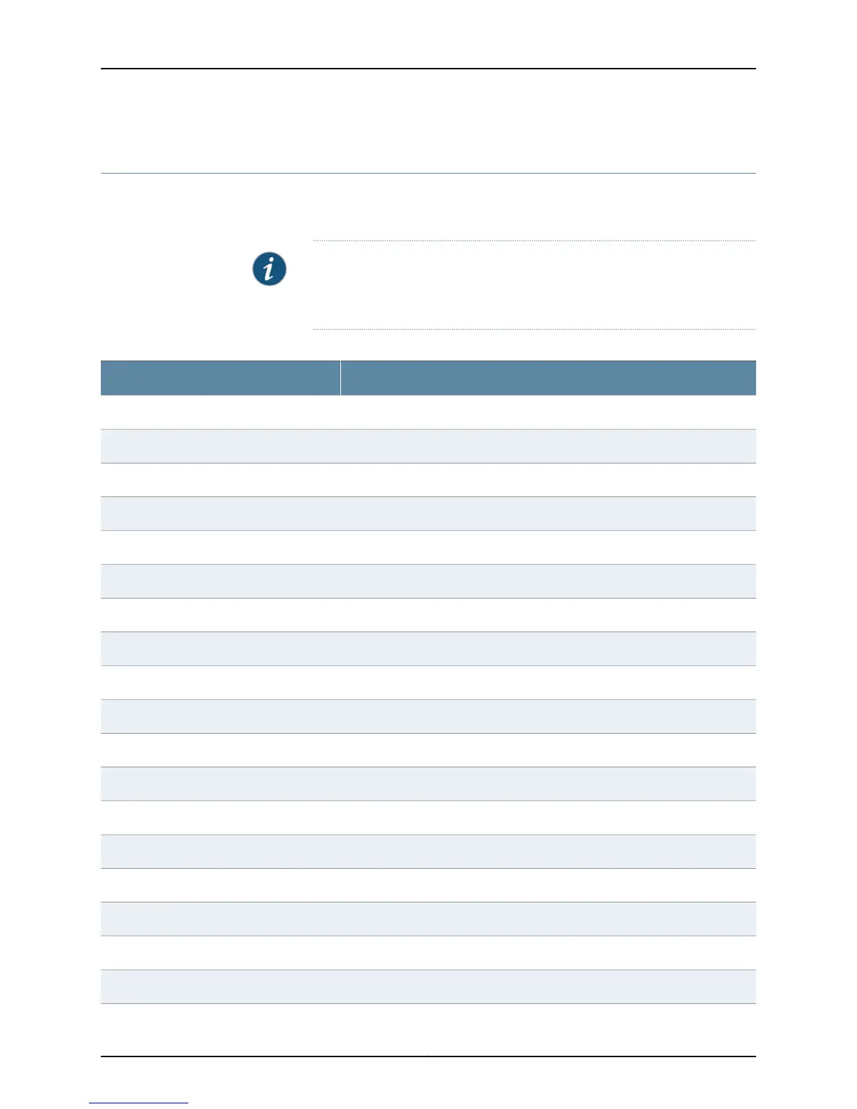
Table 49 on page 130 provides the uplink modules connector pinout information.
NOTE: You can use these ports to connect an access switch to a distribution
switch. You can also use optional uplink module ports to connect members
of a Virtual Chassis across multiple wiring closets.
Table 49: Uplink Modules Connector Pinout Information
Pin NamePin Number
GNDA1
GNDA2
GNDA3
GNDA4
GNDA5
GNDA6
GNDA7
GNDA8
GNDA9
GNDA10
GNDA11
GNDA12
GNDA13
GNDA14
Uplink_I2C_SCKA15
GNDA16
Uplink_PDA17
GNDA18
Copyright © 2015, Juniper Networks, Inc.130
EX4200 Switch Hardware Guide

Table of Contents

Other manuals for Juniper EX4200

Questions and Answers:

Question and Answer IconNeed help?

Do you have a question about the Juniper EX4200 and is the answer not in the manual?

Juniper EX4200 Specifications

General IconGeneral
ModelEX4200
Switching Capacity128 Gbps
LayerLayer 2 and Layer 3
Form Factor1U
Throughput96 Mpps
Maximum VLANs4096
MAC Address Table Size16, 000
DRAM1 GB
Flash Memory1 GB
Forwarding Rate96 Mpps
JUNOS SoftwareYes
Ports24 or 48
StackingUp to 10 switches in a Virtual Chassis configuration
Power SupplyAC or DC
ManagementCLI, SNMP, J-Web
Input Voltage100-240 VAC or -48 VDC
Operating Temperature0°C to 45°C
RedundancyRedundant power supplies
Virtual Chassis TechnologyYes
Storage Temperature-40°C to 70°C
Humidity5% to 90% non-condensing

Related product manuals