NOTE: The DC power supply in the switch has four terminals labeled A+,
B+, A–, and B– (see Figure 43 on page179) forconnecting DC powersource
cables labeled positive (+) and negative (–). The DC power supplies are
shipped with jumpers from A+ input toB+ input tied together and jumpers
from A– input to B– input tied together.
NOTE: The A+ and B+ terminals are referred to as +RTN and A– and B–
terminals arereferredtoas–48 V in“DC Power Wiring Sequence Warning”
on page 310 and “DC Power Electrical Safety Guidelines” on page 306.
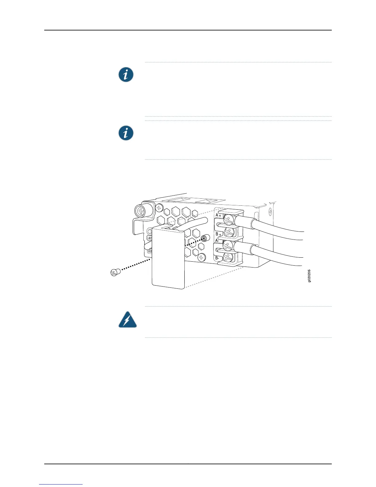
3. Remove the screw securing the terminal block cover using the screwdriver and remove
the terminal block cover (see Figure 44 on page 181). Save the screw.
Figure 44: Removing the Terminal Block Cover from a DC Power Supply
4. Remove the screws on the terminals using the screwdriver. Save the screws.
WARNING: Ensure that the power cables do not block access to switch
components or drape where people can trip on them.
5. Connect the power supplies to the power sources. Secure power source cables to the
power supplies by screwing the ring lugs attached to the cables to the appropriate
terminals by using the screw from the terminals (see Figure 45 on page 182).
•
To connect a power supply to a power source:
a. Leave the jumpers on the power supply terminals in place.
b. Secure the ring lug of the positive (+) DC power source cable to the A+ or B+
terminal on the DC power supply.
181Copyright © 2015, Juniper Networks, Inc.
Chapter 13: Connecting the Switch to Power