EasyManuals Logo

Juniper EX4200 User Manual

Juniper EX4200
344 pages
To Next Page IconTo Next Page
To Previous Page IconTo Previous Page
Page #47 background imageLoading...
Page #47 background image
Figure 13 on page 26 shows the location of the LEDs on the uplink module ports on the
SFP+ and SFP+ MACsec uplink modules.
Figure 14 on page 26 shows the location of the LEDs on the uplink module ports on the
XFP uplink module.
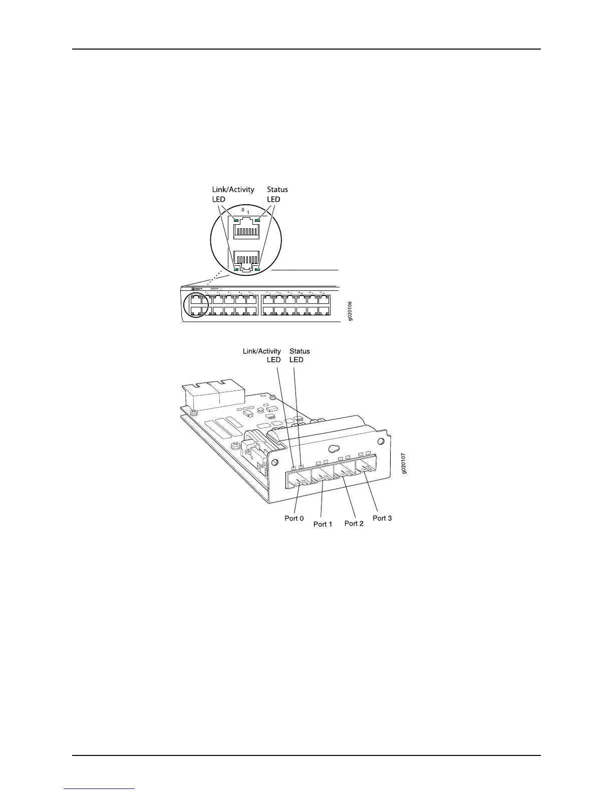
Figure 11: LEDs on the Network Ports on the Front Panel
Figure 12: LEDs on the Uplink Module Ports on the SFP Uplink Module
25Copyright © 2015, Juniper Networks, Inc.
Chapter 2: Chassis Components and Descriptions

Table of Contents

Other manuals for Juniper EX4200

Questions and Answers:

Question and Answer IconNeed help?

Do you have a question about the Juniper EX4200 and is the answer not in the manual?

Juniper EX4200 Specifications

General IconGeneral
ModelEX4200
Switching Capacity128 Gbps
LayerLayer 2 and Layer 3
Form Factor1U
Throughput96 Mpps
Maximum VLANs4096
MAC Address Table Size16, 000
DRAM1 GB
Flash Memory1 GB
Forwarding Rate96 Mpps
JUNOS SoftwareYes
Ports24 or 48
StackingUp to 10 switches in a Virtual Chassis configuration
Power SupplyAC or DC
ManagementCLI, SNMP, J-Web
Input Voltage100-240 VAC or -48 VDC
Operating Temperature0°C to 45°C
RedundancyRedundant power supplies
Virtual Chassis TechnologyYes
Storage Temperature-40°C to 70°C
Humidity5% to 90% non-condensing

Related product manuals