EasyManuals Logo

Juniper EX4200 User Manual

Juniper EX4200
344 pages
To Next Page IconTo Next Page
To Previous Page IconTo Previous Page
Page #241 background imageLoading...
Page #241 background image
CAUTION: Ensure the screwdriver does not slip out of the keyhole when
you pull the uplink module out of the switch chassis.
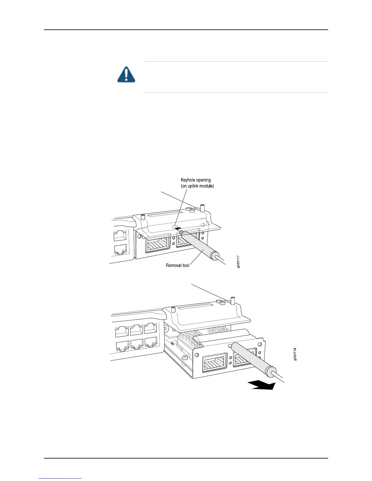
4. Using both hands, gently pull the screwdriver to slide the uplink module halfway out
of the chassis (see Figure 60 on page 219).
5. Place one hand under the uplink module to support it and slide it completely out of
the chassis.
6. Slide the screwdriver out of the keyhole.
7. Place the uplink module in an antistatic bag or on an antistatic mat placed on a flat,
stable surface.
Figure 59: Sliding the Screwdriver to the Narrow Part of the Keyhole
Figure 60: Removing an Uplink Module from an EX4200 Switch
Related
Documentation
Installing an Uplink Module in an EX4200 Switch on page 215
Installing and Removing EX4200 Switch Hardware Components on page 169
Field-Replaceable Units in EX4200 Switches on page 10
219Copyright © 2015, Juniper Networks, Inc.
Chapter 18: Replacing Uplink Module

Table of Contents

Other manuals for Juniper EX4200

Questions and Answers:

Question and Answer IconNeed help?

Do you have a question about the Juniper EX4200 and is the answer not in the manual?

Juniper EX4200 Specifications

General IconGeneral
ModelEX4200
Switching Capacity128 Gbps
LayerLayer 2 and Layer 3
Form Factor1U
Throughput96 Mpps
Maximum VLANs4096
MAC Address Table Size16, 000
DRAM1 GB
Flash Memory1 GB
Forwarding Rate96 Mpps
JUNOS SoftwareYes
Ports24 or 48
StackingUp to 10 switches in a Virtual Chassis configuration
Power SupplyAC or DC
ManagementCLI, SNMP, J-Web
Input Voltage100-240 VAC or -48 VDC
Operating Temperature0°C to 45°C
RedundancyRedundant power supplies
Virtual Chassis TechnologyYes
Storage Temperature-40°C to 70°C
Humidity5% to 90% non-condensing

Related product manuals