Ensure that you have the following parts and tools available:
•
Phillips (+) screwdriver, number 2
•
2 mounting brackets and 8 mounting screws (provided in the accessory box shipped
with the switch)
•
Screws to secure the chassis to the rack (not provided)
•
2-in.-recess front brackets if you will mount the switch in a recessed position (brackets
are from the separately orderable four-post rack-mount kit).
•
Dust covers for ports (for EX4200-24F switches only; optional)
NOTE: One person must be available to lift the switch while another secures
the switch to the rack.
CAUTION: If you are mounting multiple switches on a rack, mount a switch
in the bottom of the rack first and proceed to mount the rest of the switches
from bottom to top.
To mount the switch on two posts in a rack:
1. Place the switch on a flat, stable surface.
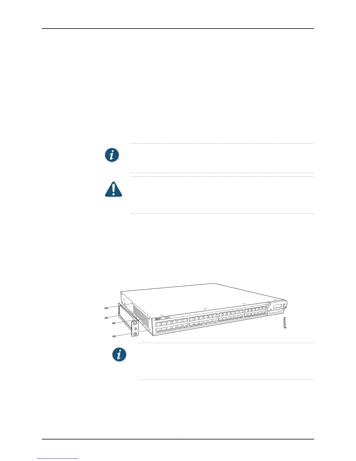
2. Align the mounting brackets along the front, rear, or center of the side panels of the
switch chassis depending on how you want to mount the switch. For example, if you
want to front-mount the switch, align the brackets along the front of the side panel.
See Figure 31 on page 161.
Figure 31: Attaching the Mounting Bracket to the Side Panel of the Switch
NOTE: If you need to mount the switch in a recessed position, use the
2-in.-recess front mount brackets from the separately orderablefour-post
rack-mount kit.
3. Align the bottom holes in the mounting brackets with holes on the side panels of the
switch chassis.
4. Insert mounting screws into the aligned holes. Tighten the screws.
161Copyright © 2015, Juniper Networks, Inc.
Chapter 12: Installing the Switch