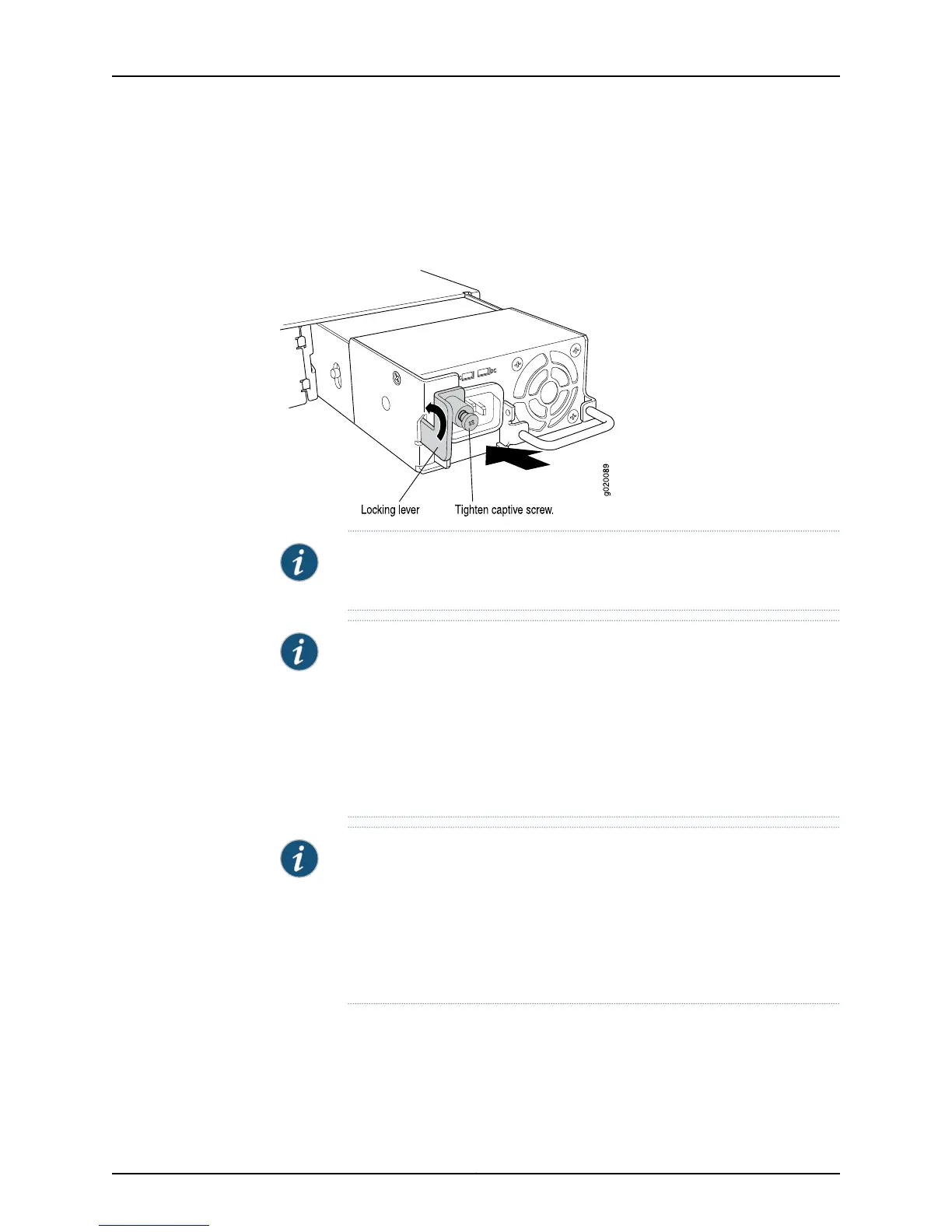
5. Push the locking lever up to its highest position (this action might pull the power supply
in).
6. Tighten the locking lever screw by using the screwdriver.
Figure 56: Installing a Power Supply in an EX4200 Switch
NOTE: Each power supply must be connected to a dedicated power source
outlet.
NOTE: EX4200-24PX and EX4200-48PX switches do not support the 930
W (EX-PWR-930-AC) or the 600 W (EX-PWR-600-AC) AC power supplies
that are used in the EX4200-48P and the EX4200-24P switch models.
EX4200-24PX and EX4200-48PX switches work only with the power supply
labeled EX-PWR2-930-AC. You can find the label on the top of the power
supply (see“Removing aPowerSupply froman EX4200 Switch” on page 213).
TheEX-PWR2-930-AC power supply issupportedacrossthe EX4200 product
line.
NOTE: If you have a Juniper J-Care service contract, register any addition,
change, or upgrade of hardware components at
https://www.juniper.net/customers/csc/management/updateinstallbase.jsp .
Failure to do so can result in significant delays if you need replacement parts.
This note applies if you change the type of power supply or add a new type
of uplink module. It does not apply if you replace these components with the
same type of component.
Related
Documentation
Removing a Power Supply from an EX4200 Switch on page 213•
• Installing and Removing EX4200 Switch Hardware Components on page 169
• Power Supply in EX4200 Switches on page 33
Copyright © 2015, Juniper Networks, Inc.212
EX4200 Switch Hardware Guide