CHAPTER 3
Cooling System and Airflow
•
Cooling System and Airflow in an EX4200 Switch on page 31
Cooling System and Airflow in an EX4200 Switch
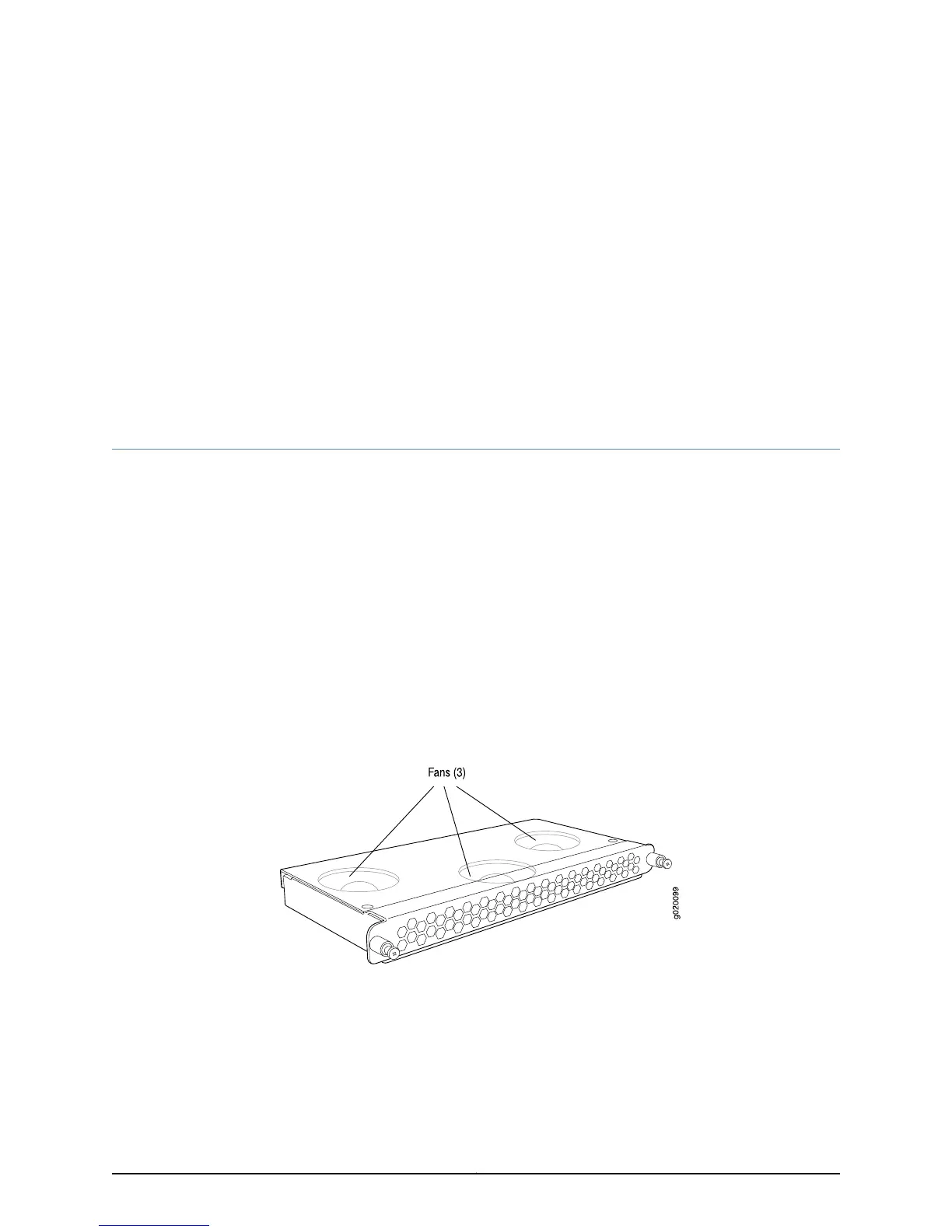
The cooling system in an EX4200 switch consists of a field-replaceable unit (FRU) fan
tray with three fans (see Figure 15 on page 31). All the EX4200 switch models, except
the EX4200-24F-S and EX4200-48T-S switches are shipped with one fan tray
pre-installed in the rear panel of the switches. EX4200-24F-S and EX4200-48T-S
switches are not shipped with pre-installed fan tray; you must order them separately.
This topic describes:
•
Fan Tray on page 31
•
Airflow Direction in the EX4200 Switch Chassis on page 31
Fan Tray
The fan tray is located at the rear of the chassis.
Figure 15: Fan Tray Used in an EX4200 Switch
Airflow Direction in the EX4200 Switch Chassis
The fan tray located at the rear of the chassis provides side-to-rear chassis cooling (see
Figure 16 on page 32).
31Copyright © 2015, Juniper Networks, Inc.