EasyManuals Logo

Juniper EX4200 User Manual

Juniper EX4200
344 pages
To Next Page IconTo Next Page
To Previous Page IconTo Previous Page
Page #201 background imageLoading...
Page #201 background image
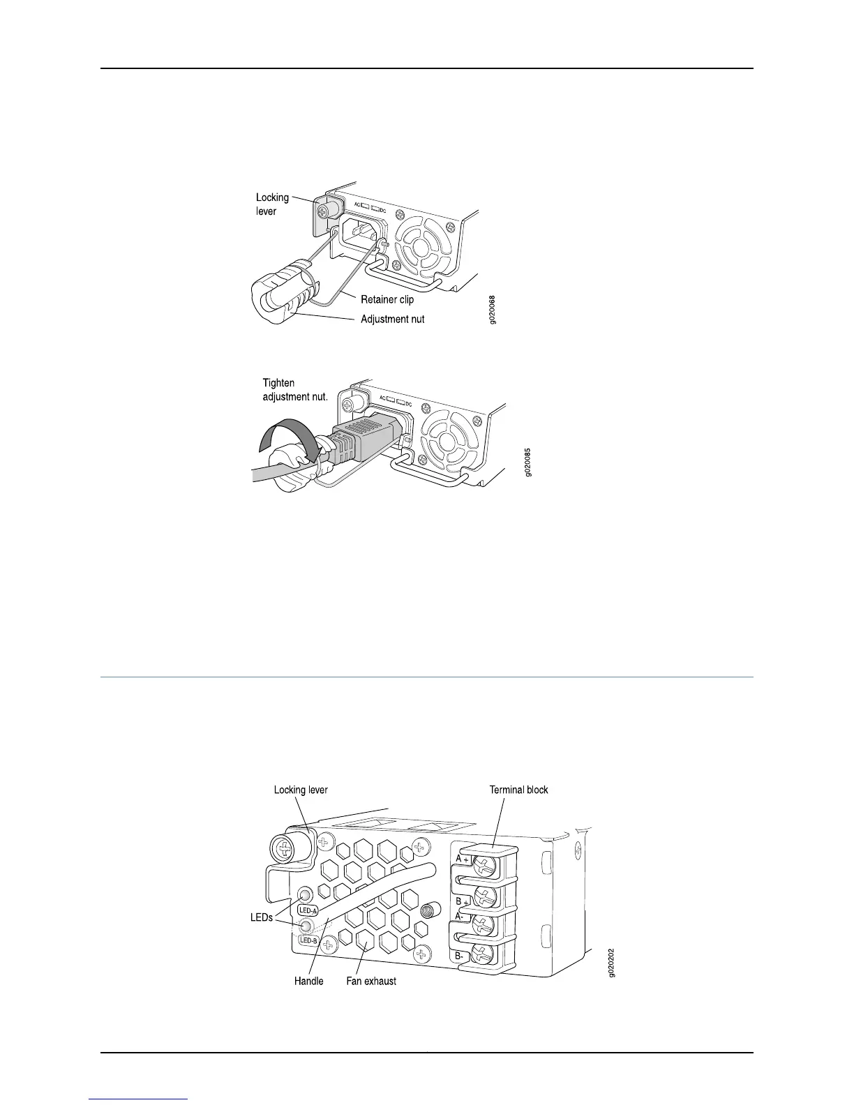
Figure 41: Connecting the AC Power Cord Retainer Clip to an AC Power
Supply in an EX4200 Switch
Figure 42: Connecting an AC Power Cord to an AC Power Supply in an
EX4200 Switch
Related
Documentation
Connecting and Configuring an EX Series Switch (CLI Procedure) on page 195
Connecting and Configuring an EX Series Switch (J-Web Procedure) on page 198
Connecting DC Power to an EX4200 Switch on page 179
Power Supply in EX4200 Switches on page 33
AC Power Supply LEDs in EX4200 Switches on page 37
Connecting DC Power to an EX4200 Switch
The power supply in an EX4200 switch is a hot-removable and hot-insertable
field-replaceable unit (FRU) located on the rear panel: You can remove and replace it
without powering off the switch or disrupting switch functions.
Figure 43: DC Power Supply in an EX4200 Switch
179Copyright © 2015, Juniper Networks, Inc.
Chapter 13: Connecting the Switch to Power

Table of Contents

Other manuals for Juniper EX4200

Questions and Answers:

Question and Answer IconNeed help?

Do you have a question about the Juniper EX4200 and is the answer not in the manual?

Juniper EX4200 Specifications

General IconGeneral
ModelEX4200
Switching Capacity128 Gbps
LayerLayer 2 and Layer 3
Form Factor1U
Throughput96 Mpps
Maximum VLANs4096
MAC Address Table Size16, 000
DRAM1 GB
Flash Memory1 GB
Forwarding Rate96 Mpps
JUNOS SoftwareYes
Ports24 or 48
StackingUp to 10 switches in a Virtual Chassis configuration
Power SupplyAC or DC
ManagementCLI, SNMP, J-Web
Input Voltage100-240 VAC or -48 VDC
Operating Temperature0°C to 45°C
RedundancyRedundant power supplies
Virtual Chassis TechnologyYes
Storage Temperature-40°C to 70°C
Humidity5% to 90% non-condensing

Related product manuals