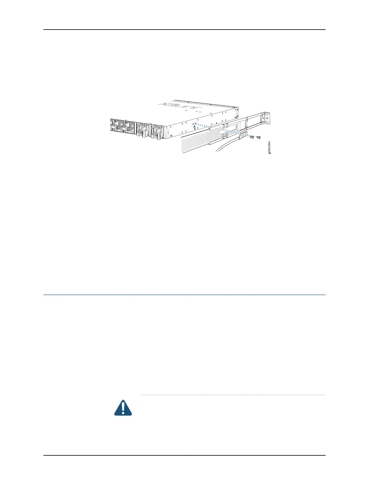
1. Secure the provided protective earthing terminal bracket through the EX4600 switch
mounting bracket to the chassis with the nut provided. The posts on the protective
earthing terminal bracket should point to the left. See Figure 21 on page 147.
Figure 21: Connecting a Grounding Cable to an EX4600 Switch
2. Connect one end of the grounding cable to a proper earth ground, such as the rack in
which the switch is mounted.
3. Place the grounding lug attached to the grounding cable over the protective earthing
terminal on the protective earthing terminal bracket.
4. Secure the grounding lug to the protective earthing terminal with two nuts.
5. Dress the grounding cable and ensure that it does not touch or block access to other
device components and that it does not drape where people could trip over it.
Related
Documentation
General Safety Guidelines and Warnings on page 91•
• Grounded Equipment Warning on page 112
• Connecting AC Power to an EX4600 Switch on page 147
• Connecting DC Power to an EX4600 Switch on page 149
Connecting AC Power to an EX4600 Switch
The power supply in an EX4600 switch is a hot-removable and hot-insertable
field-replaceable unit (FRU). You can remove and replace it without powering off the
switch or disrupting switch functions.
Ensure that you have a power cord appropriate for your geographical location available
to connect AC power to the switch.
Before you begin connecting AC power to the switch:
•
Ensure that you have taken the necessary precautions to prevent electrostatic discharge
(ESD) damage (see “Prevention of Electrostatic Discharge Damage” on page 120).
•
Ensure that you have connected the switch chassis to earth ground.
CAUTION: Before you connect power to the switch, a licensed electrician
must attach a cablelug to the grounding and power cables that you supply.
147Copyright © 2014, Juniper Networks, Inc.
Chapter 17: Connecting the EX4600 Device