Fan Module LED on an EX4600 Switch
Figure 43 on page 194 shows the location of the LED next to the fan module.
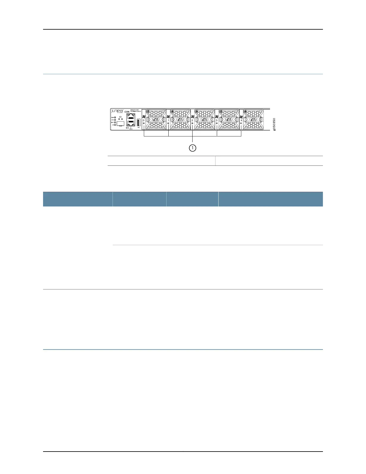
Figure 43: Fan Module LED in an EX4600 Switch
1— Fan LED
Table 40 on page 194 describes the function of the fan tray LED.
Table 40: Fan Tray LED in an EX4600 Switch
DescriptionStateColorName
The fan module is operating normally. The
system has verified that the module is
engaged, that the airflow is in the correct
direction, and that the fan is operating
correctly.
On steadilyGreenFan
An error has been detected in the fan module.
Replace the fan module as soon as possible.
Either the fan has failed or it is seated
incorrectly.To maintain proper airflow through
the chassis, leave the fan module installed in
the chassis until you are ready to replace it.
BlinkingAmber
Related
Documentation
Cooling System and Airflow in an EX4600 Switch on page 13•
• Installing a Fan Module in an EX4600 Switch on page 174
• Removing a Fan Module from an EX4600 Switch on page 176
AC Power Supply LEDs on an EX4600 Switch
Figure 44 on page 195 shows the location of the LEDs on the power supply.
Copyright © 2014, Juniper Networks, Inc.194
EX4600 Switch Hardware Guide