you install power supplies with two different airflow directions, Junos OS
raises an alarm, and the status (ALM) LED blinks amber.
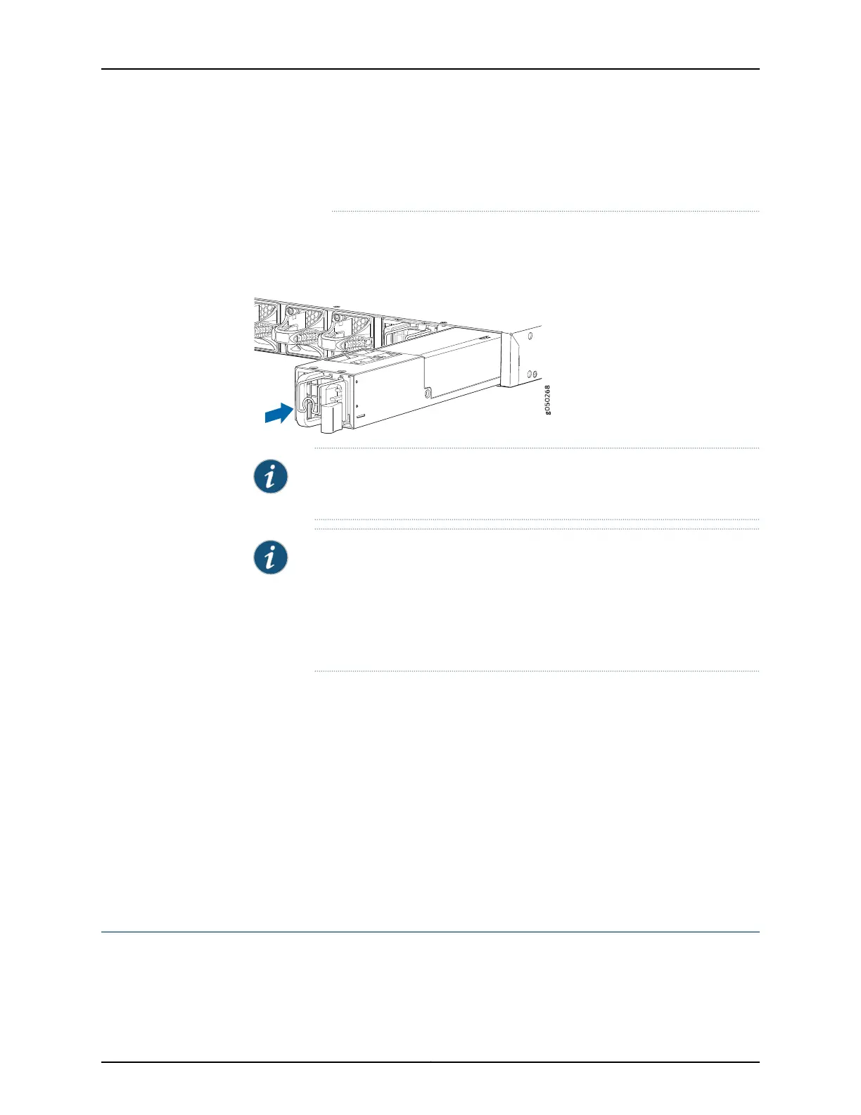
3. Using both hands, place the power supply in the power supply slot on the FRU panel
of the switch and slide it in until it is fully seated and the locking lever slides into place.
Figure 30: Installing a Power Supply in an EX4600 Switch
QFX5100-48S
RUNNING JUN OS
NOTE: Each power supply must be connected to a dedicated power source
outlet.
NOTE: If you have a Juniper J-Care service contract, register any addition,
change, or upgrade of hardware components at
https://www.juniper.net/customers/csc/management/updateinstallbase.jsp .
Failure to do so can result in significant delays if you need replacement parts.
This note does not apply if you replace components with the same type of
component.
Related
Documentation
AC Power Supply in an EX4600 Switch on page 23•
• Field-Replaceable Units in an EX4600 Switch on page 6
• Port Panel of an EX4600 Switch on page 11
• Management Panel of an EX4600 Switch on page 9
• AC Power Cord Specifications for an EX4600 Switch on page 79
• Connecting AC Power to an EX4600 Switch on page 147
• Connecting DC Power to an EX4600 Switch on page 149
• Removing a Power Supply from an EX4600 Switch on page 169
Removing a Power Supply from an EX4600 Switch
The power supplies in an EX4600 switch are hot-removable and hot-insertable
field-replaceable units (FRUs): you can remove and replace them without powering off
the switch or disrupting switch functions.
169Copyright © 2014, Juniper Networks, Inc.
Chapter 20: Replacing Components