EasyManuals Logo

Juniper EX4600 Series User Manual

Juniper EX4600 Series
230 pages
To Next Page IconTo Next Page
To Previous Page IconTo Previous Page
Page #210 background imageLoading...
Page #210 background image
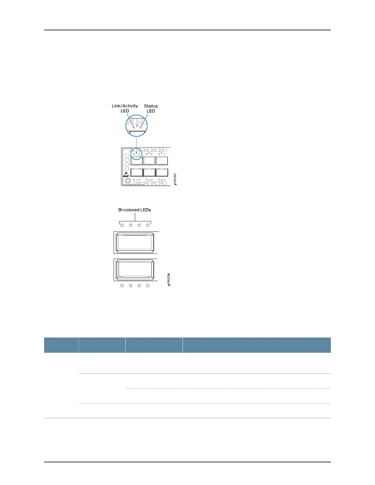
Figure 41 on page 192 shows the location of the LEDs on the SFP+ access ports on the
EX4600 and Figure 42 on page 192 showsthe location of the LEDs on the QSFP+ uplink
ports on the EX4600.
Figure 41: LEDs on the SFP+ Ports
Figure 42: LEDs on the QSFP+ Ports
The LED in Figure 41 on page 192 labeled Link/Activity indicate link activity or a fault. The
LED labeled Status in indicates transceiver presence.
Table 38 on page 192 describes how to interpret the SFP+ port LEDs.
Table 38: Network Port LEDs on SFP+ Ports on an EX4600 Switch
DescriptionStateColorLED
The port is administratively disabled, there is no power, the link
is down, or there is a fault.
OffUnlitLink/Activity
A link is established, but there is no link activity.On steadilyGreen
A link is established, and there is link activity.Blinking
The beacon is enabled on the port.BlinkingAmber
Copyright © 2014, Juniper Networks, Inc.192
EX4600 Switch Hardware Guide

Table of Contents

Questions and Answers:

Question and Answer IconNeed help?

Do you have a question about the Juniper EX4600 Series and is the answer not in the manual?

Juniper EX4600 Series Specifications

General IconGeneral
Product SeriesEX4600
10GbE ports24 or 48
CoolingFront-to-back or back-to-front airflow
Rack Units1 U
Virtual ChassisUp to 10 members
MAC address table size288, 000 entries
Memory8 GB DRAM
Layer 3 RoutingYes
AC Power Input100-240V AC
Ports24 or 48 x 10GbE ports
40GbE ports4
100GbE ports0
Power SupplyDual redundant, hot-swappable AC or DC
Jumbo frames9216 bytes
Operating temperature0°C to 45°C
Input voltage100-240 VAC, -40 to -72 VDC
Operating relative humidity5% to 90% noncondensing
FansRedundant
JUNOS OSJunos OS
Storage16 GB flash
DC Power Input-40 to -72 VDC

Related product manuals