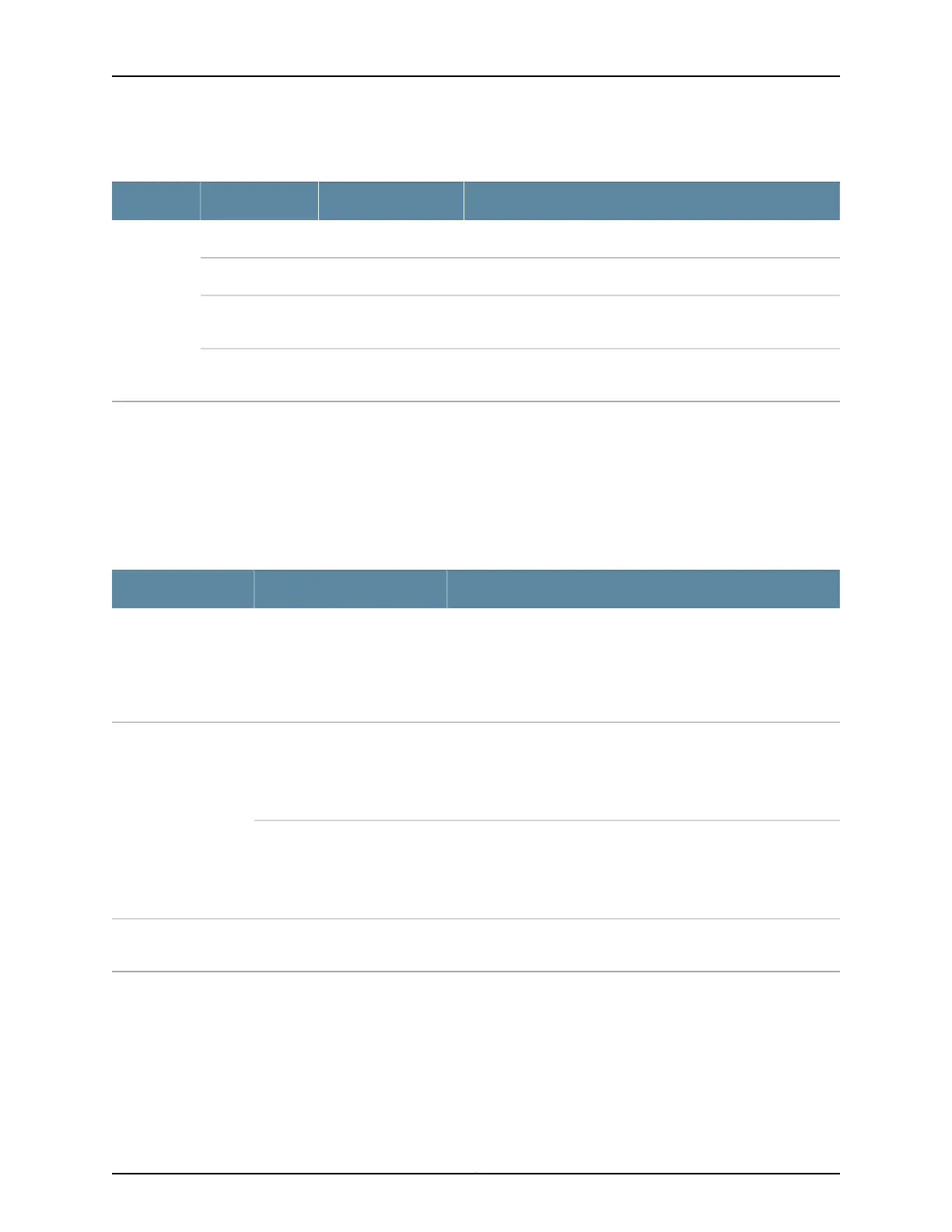
Table 38: Network Port LEDs on SFP+ Ports on an EX4600 Switch (continued)
DescriptionStateColorLED
The link is down.OffUnlitStatus
The beacon function is enabled on the port.BlinkingAmber
A 1-Gigabit Ethernet transceiver is installed in the port and the
link is established.
BlinkingGreen
A 10-Gigabit Ethernet transceiver is installed in the port and link
is established.
On steadilyGreen
As shown in Figure 42 on page 192, there are four bi-color LEDs for each QSFP+ port. The
first LED is used and the remaining LEDs are not used when the interface is configured
for 40-Gigabit Ethernet and connected to a QSFP+ transceiver. All four LEDs are used
when the interface is configured for 10-Gigabit Ethernet and the port is connected using
an optical split cable or a copper DACBO cable. Table 39 on page 193 describes how to
interpret the QSFP+ LEDs.
Table 39: Network Port LEDs on QSFP+ Ports on an EX4600 Switch
DescriptionStateColor
The port is administratively disabled, there is no power, the link is
down, or there is a fault.
NOTE: When configured for 10-Gigabit Ethernet, the LED remains
unlit only if all four of the 10-Gigabit Ethernet SFP+ breakout links
are down.
OffUnlit
A link is established, but there is no link activity.
NOTE: When configured for 10-Gigabit Ethernet, the LED is lit green
when at least one of the four 10-Gigabit Ethernet SFP+ breakout
links is established.
On steadilyGreen
A link is established, and there is link activity.
NOTE: When configured for 10-Gigabit Ethernet, the LED is lit green
when at least one of the four 10-Gigabit Ethernet SFP+ breakout
links is established.
Blinking
All four LEDs blink to indicate the beacon function was enabled on
the port.
BlinkingAmber
Related
Documentation
Management Panel of an EX4600 Switch on page 9•
• Installing a Transceiver in an EX Series Switch on page 182
• Connecting a Fiber-Optic Cable to an EX Series Switch on page 184
193Copyright © 2014, Juniper Networks, Inc.
Chapter 23: Viewing System Information