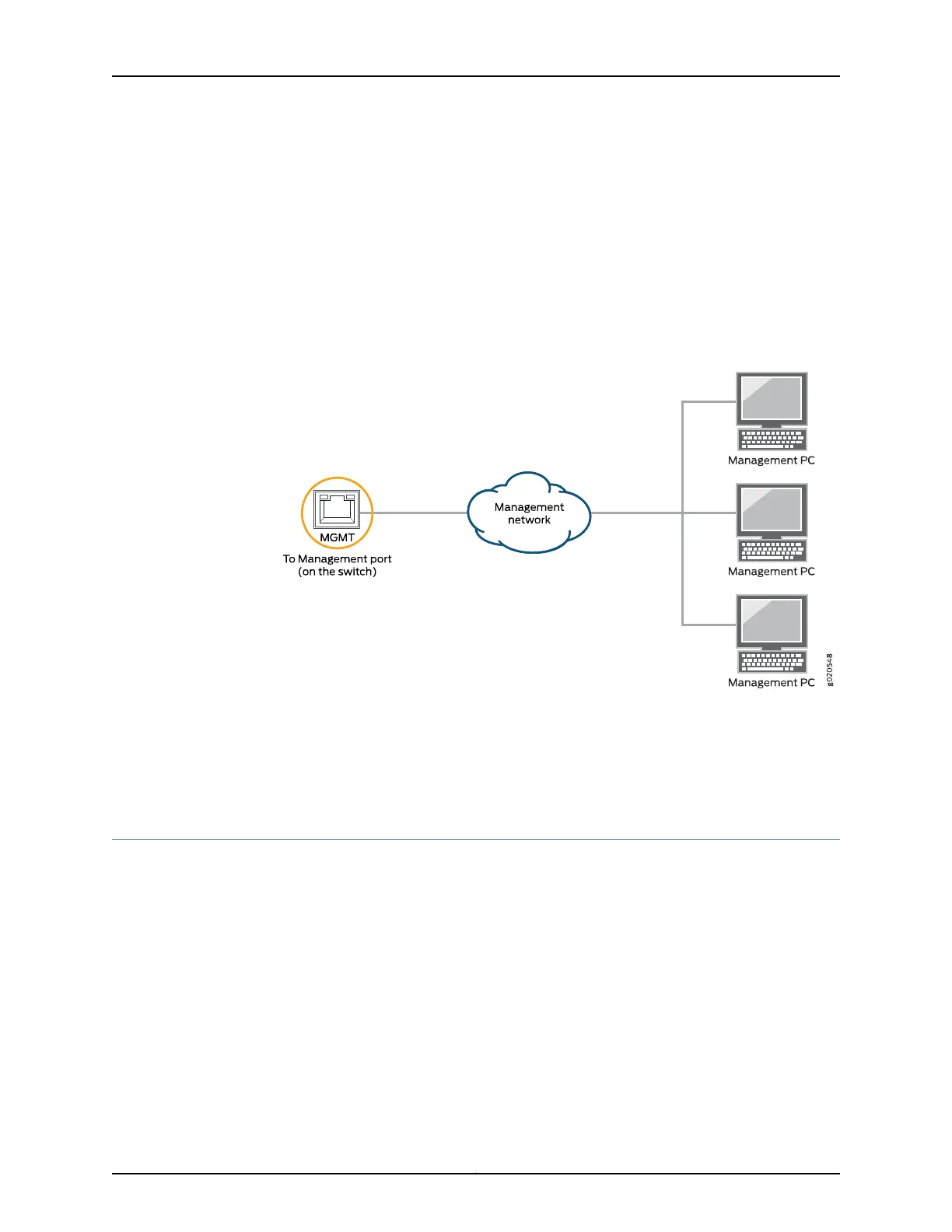
To connect a EX4600 switch to a network for out-of-band management (see
Figure 28 on page 156):
1. Connect one end of the cable to one of the management ports (labeled C0 and
C1) on the EX4600 switch.
2. Connect the other end of the cable to the management switch (see
Figure 28 on page 156).
Figure 28: Connecting an EX4600 Switch to a Network for Out-of-Band
Management
Related
Documentation
Management Panel of an EX4600 Switch on page 9•
• Network Cable Specifications for EX4600 Switches on page 73
• Connecting an EX Series Switch to a Management Console on page 153
Connecting EX4600 Switches in a Virtual Chassis
EX4600 switches can be cabled together to create a Virtual Chassis in a ring topology.
Each Virtual Chassis can have up to 10 switches (members) participating in the ring. The
Virtual Chassis can be comprised of all EX4600 switches filling the master Routing Engine
(RE), backup RE, and linecard roles. You can also add EX4300 switches to the Virtual
Chassis in the linecard role, but is not recommended as a master or backup.
Virtual Chassis can be installed in a single rack, multiple rack, or in wire closets.
You configure an EX4600 Virtual Chassis by configuring the SFP+ or QSFP+ interfaces
into Virtual Chassis ports (VCPs). VCPs connect switches together to form a Virtual
Chassis, and are responsible for passing all data and control traffic between member
switches in the VirtualChassis. All non-channelized QSFP+ uplink interfaceson standalone
Copyright © 2014, Juniper Networks, Inc.156
EX4600 Switch Hardware Guide