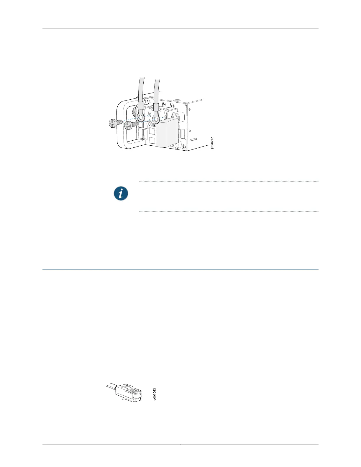
Figure 24: Securing Ring Lugs to the Terminals on the EX4600 DC Power
Supply
8. Replace the terminal block cover.
9. Close the input circuit breaker.
NOTE: The switch powers on as soon as power is provided to the power
supply. There is no power switch on the device.
10. Verify that the IN and OUT LEDs on the power supply are lit green and are on steadily.
Related
Documentation
DC Power Supply in an EX4600 Switch on page 25•
• DC Power Supply LEDs on an EX4600 Switch on page 195
Connecting an EX Series Switch to a Management Console
This topic applies to multiple hardware devices in the EX Series product family, which
includes switches and the XRE200 External Routing Engine.
You can configure and manage these devices by using a dedicated console. Every device
has a console port with an RJ-45 connector. Use the console port to connect the device
to the management console or to a console server. The console port accepts a cable
with an RJ-45 connector.
Ensure that you have an Ethernet cable with an RJ-45 connector available. An RJ-45
cable and an RJ-45 to DB-9 serial port adapter are supplied with the device.
Figure 25 on page 153 shows the RJ-45 connector of the Ethernet cable supplied with the
device.
Figure 25: Ethernet Cable Connector
153Copyright © 2014, Juniper Networks, Inc.
Chapter 17: Connecting the EX4600 Device

 Loading...


