Table 6: Fan Modules for EX4600 Switches (continued)
Power
Supplies
Direction of
Airflow in the
Fan Module
Color of
Fan
Module
Label on
the Fan
ModuleAirflow DiagramFan Module
You must install
only power
supplies that
have AIR OUT
labels in
switches in
which the fan
modules have
AIR OUT labels.
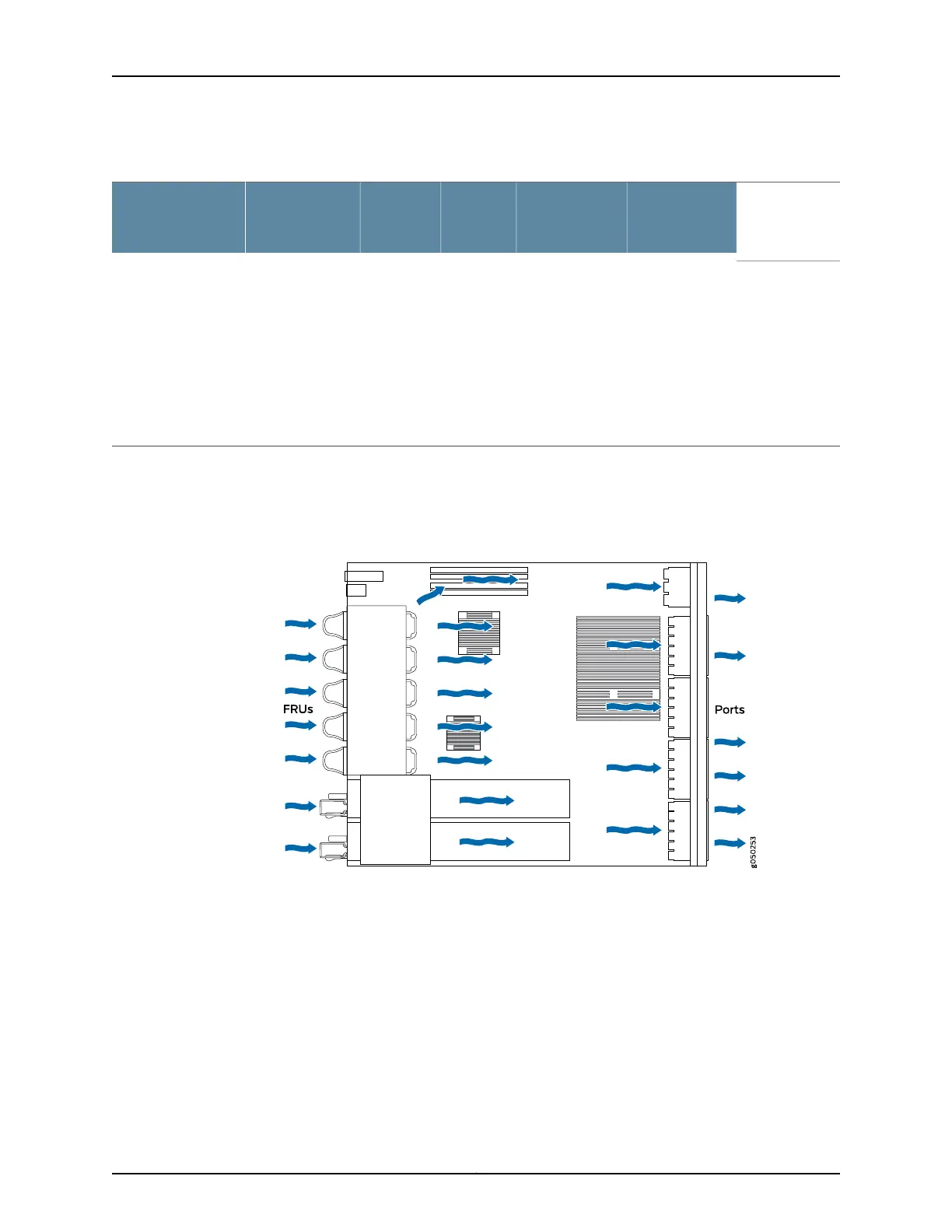
Port-to-FRU,
that is, air comes
in through vents
on the end with
ports; air
exhaustsout the
end with the
fans (also
known as
front-to-back
airflow).
Juniper
Gold
AIR OUTFigure8 on page16QFX5100-FAN-AFO
In data center deployments, position the switch in such a manner that the AIR IN labels
on switch components are next to the cold aisle, and AIR OUT labels on switch
components are next to the hot aisle.
Figure 7: Air In Airflow Through EX4600 Switch Chassis
15Copyright © 2014, Juniper Networks, Inc.
Chapter 3: Cooling System and Airflow
* Optics, Fans and Power supply sold separately for EX4600-40F-S.