CHAPTER 23
Viewing System Information
•
Chassis Status LEDs on an EX4600 Switch on page 189
•
Management Port LEDs on an EX4600 Switch on page 190
•
Access Port and Uplink Port LEDs on an EX4600 Switch on page 191
•
Fan Module LED on an EX4600 Switch on page 194
•
AC Power Supply LEDs on an EX4600 Switch on page 194
•
DC Power Supply LEDs on an EX4600 Switch on page 195
Chassis Status LEDs on an EX4600 Switch
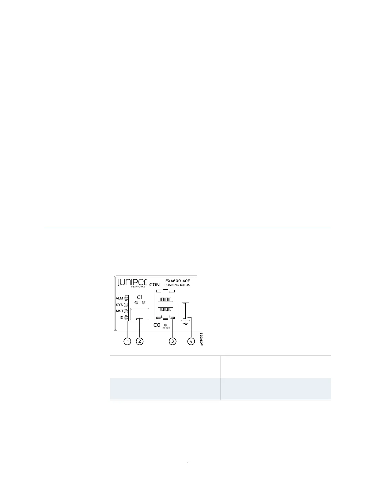
The EX4600 switch has four status LEDs on the field-replaceable unit (FRU) end of the
chassis, next to the management ports (see Figure 39 on page 189).
Figure 39: Chassis Status LEDs on an EX4600 Switch
3—1— em0–RJ-45 (10/100/1000 Base-T)
managementEthernetport (C0).The RJ-45
console port (CON) is above C0.
Status LEDs
4—2— USB portem1–SFP management Ethernet port (C1)
Cage (socketfor either 10/100/1000 Base-T
RJ45 SFP or 1GbE fiber SFP)
Table 36 on page 190 describes the chassis status LEDs on an EX4600 switch, their colors
and states, and the status they indicate. You can view the colors of the three LEDs
remotely through the CLI by issuing the operational mode command show chassis lcd.
189Copyright © 2014, Juniper Networks, Inc.