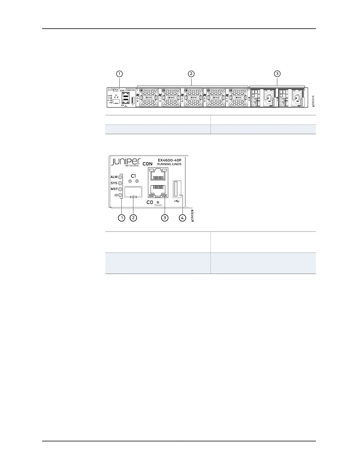
Figure 3: EX4600 Switch, FRU End
3—1— Power supply unitsManagement panel
2—Fan modules
Figure 4: Management Panel Components
3—1— RJ-45 console port (C0N) and em0–RJ-45
(1000 Base-T) management Ethernet port
(C0)
Status LEDs
4—2— USB portem1–SFP management Ethernet port (C1)
Cage (socket for either 1 GbE copper SFP or
fiber SFP)
The management panel consists of the following components:
•
Status LEDs
•
ALM–Alarm or beacon
•
Unlit indicates the switch is halted or that there is no alarm.
•
Red indicates a major alarm.
•
Amber indicates a minor alarm.
•
SYS–System
•
Unlit indicates the switch is powered off or halted.
•
Solid green indicates that Junos OS for QFX Series is loaded on the switch.
•
Blinking green indicates that the switch is a participating member in a Virtual
Chassis.
•
MST–Master in a Virtual Chassis
•
Unlit indicates the switch is standalone or is a linecardmember in a Virtual Chassis.
Copyright © 2014, Juniper Networks, Inc.10
EX4600 Switch Hardware Guide
* Optics, Fans and Power supply sold separately for EX4600-40F-S.