power supply on the other side of the chassis. This configuration provides
the commonly deployed A/B feed redundancy for the system.
a. Secure the ring lug of the positive (+) DC power source cable to the V+ terminal
on the DC power supply.
b. Secure the ring lug of the negative (–) DC power source cable to the V– terminal
on the DC power supply.
c. Tighten the screws on the power supply terminals until snug using the screwdriver.
Do not overtighten—apply between 5 in-lb (0.56 Nm) and 6 in-lb (0.68 Nm) of
torque to the screws.
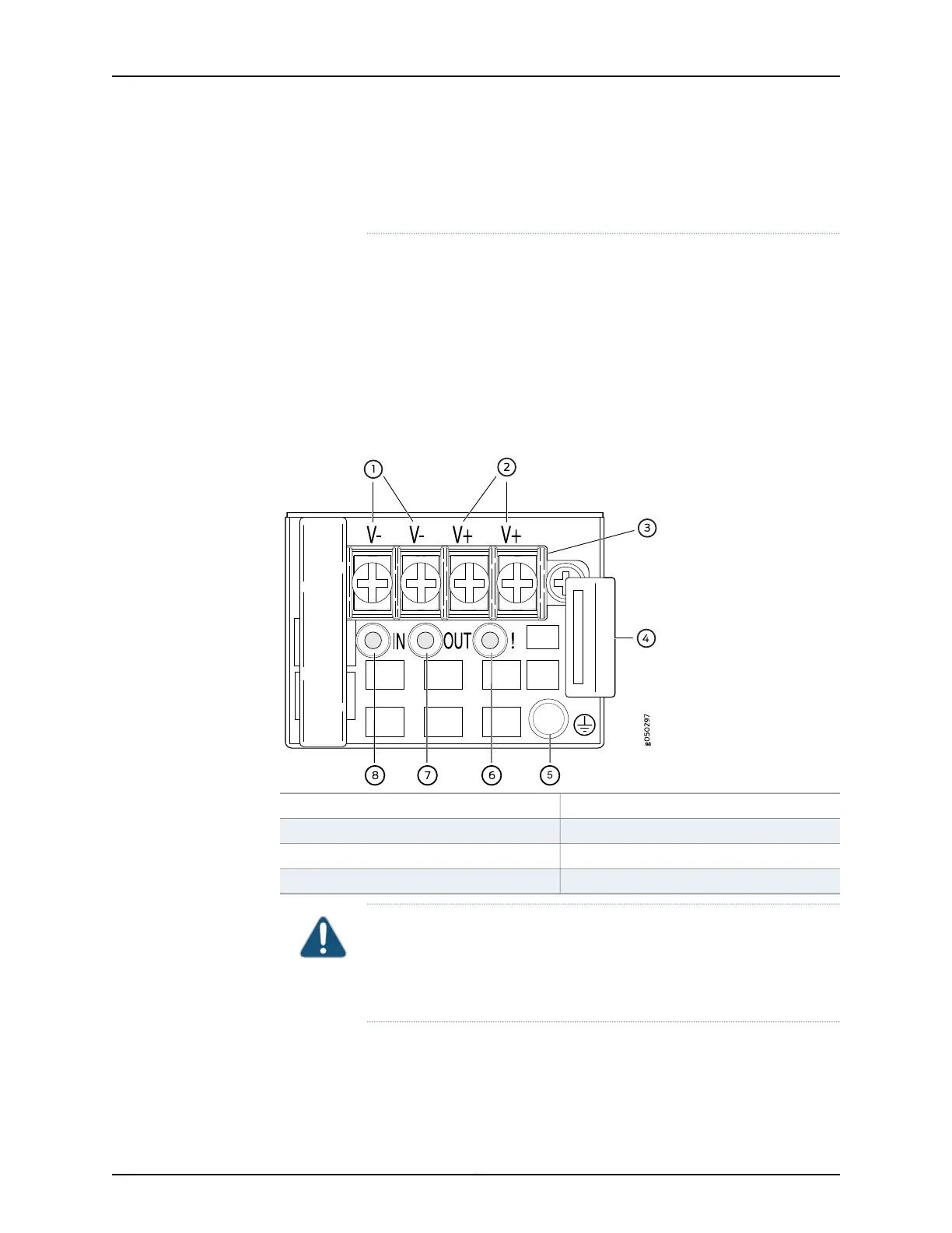
Figure 23: DC Power Supply Faceplate for an EX4600 Switch
5—1— ESD grounding pointShunt negative input terminals (+RTN)
6—2— Fault LEDShunt positive input terminals (-48V)
7—3— Output LEDTerminal block
8—4— Input LEDEjector lever
CAUTION: The V+ terminals are shunted internally together, as are the
V- terminals. The same polarity terminal can be wired together from the
same source to provide an additional current path in a higher power
chassis. Do not connect the terminals to different sources.
Copyright © 2014, Juniper Networks, Inc.152
EX4600 Switch Hardware Guide