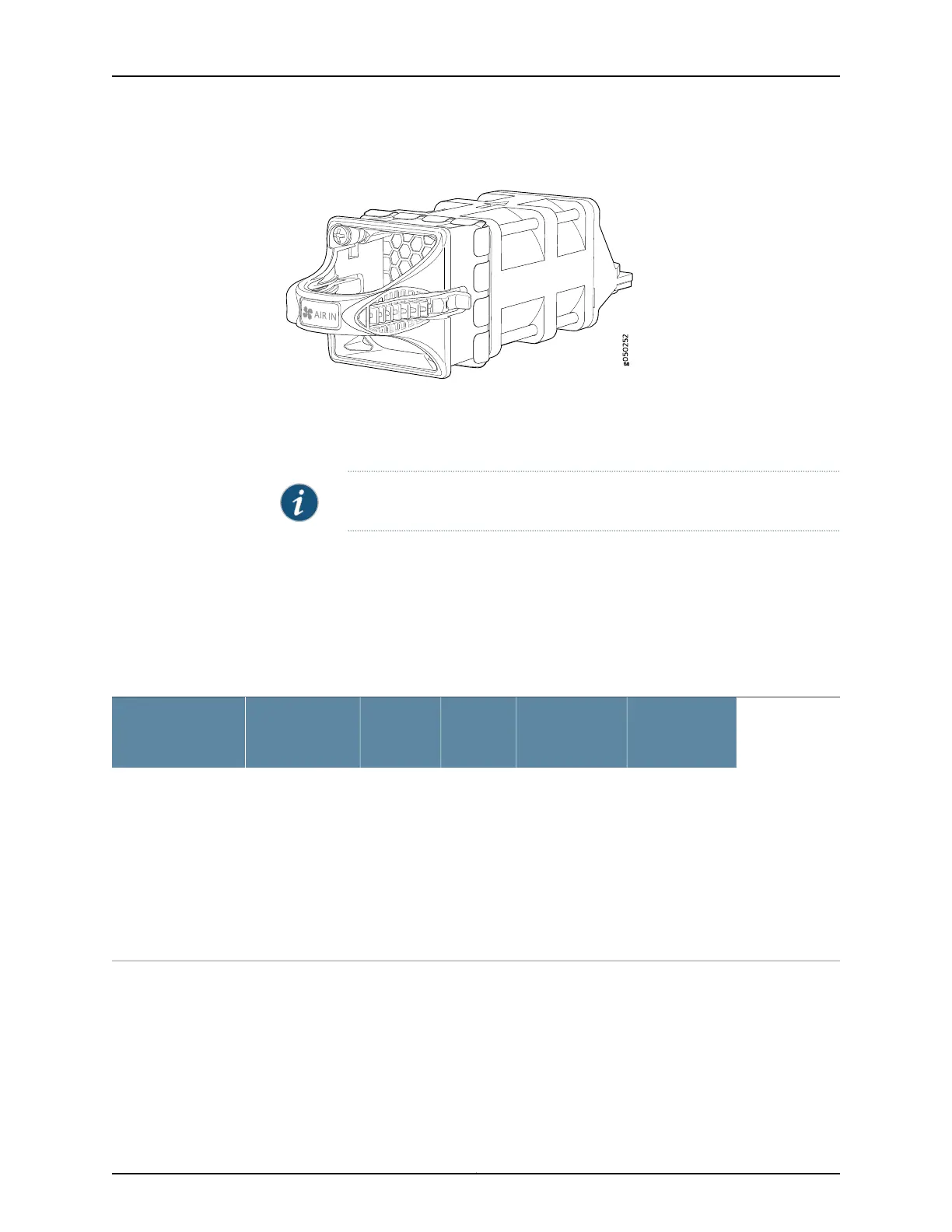
Figure 6: Fan Module for EX4600 Switches
You remove and replace a fan module from the management panel of the chassis. The
switch continues to operate for a limited period of time (30 seconds) during the
replacement of the fan module without thermal shutdown.
NOTE: All fan modules must be installed for optimal operation of the switch.
The fan modules are available in two product SKUs that have different airflow
directions—FRU-to-port airflow, indicated on some units by the blue color and the label
AIR IN , or port-to-FRU, indicated by the gold color and the label AIR OUT . On legacy
switches or switches with LCDs, this airflow is also called front-to-back and back-to-front.
Table 6 on page 14 lists the available fan module product SKUs and the direction of
airflow in them:
Table 6: Fan Modules for EX4600 Switches
Power
Supplies
Direction of
Airflow in the
Fan Module
Color of
Fan
Module
Label on
the Fan
ModuleAirflow DiagramFan Module
You must install
only power
supplies that
have AIR IN
labels in
switches in
which the fan
modules have
AIR IN labels.
FRU-to-port,
that is, air comes
in from the end
of the switch
with the fans; air
exhausts from
the switch end
with ports (also
known as
back-to-front
airflow).
Juniper
AzureBlue
AIR INFigure7onpage 15QFX5100-FAN-AFI
Copyright © 2014, Juniper Networks, Inc.14
EX4600 Switch Hardware Guide