levels. A power margin (P
M
) greater than zero indicates that the power budget is sufficient
to operate the receiver and that it does not exceed the maximum receiver input power.
This means the link will work. A (P
M
) that is zero or negative indicates insufficient power
to operate the receiver. See the specification for your receiver to find the maximum
receiver input power.
Before you begin to calculate the power margin:
•
Calculate the power budget. See “Calculating the EX Series Switch Fiber-Optic Cable
Power Budget” on page 76.
To calculate the worst-case estimate for the power margin (P
M
) for the link:
1. Determine the maximum value for link loss (LL) by adding estimated values for
applicable link-loss factors—for example, use the sample values for various factors
as provided in Table 31 on page 77 (here, the link is 2 km long and multimode, and the
(P
B
) is 13 dBm):
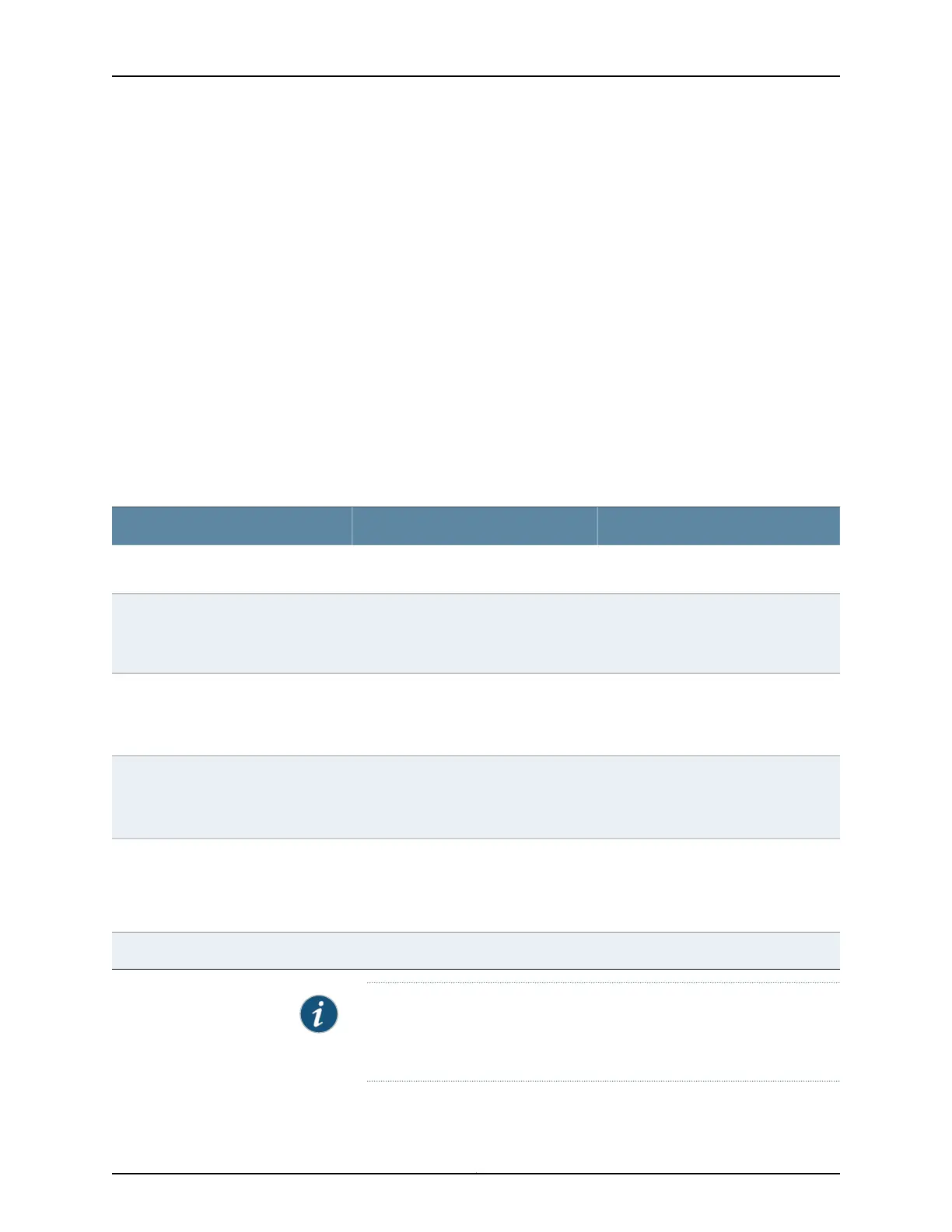
Table 31: Estimated Values for Factors Causing Link Loss
Sample (LL) Calculation ValuesEstimated Link-Loss ValueLink-Loss Factor
•
0.5 dBm
•
0 dBm
•
Multimode—0.5 dBm
•
Single mode—None
Higher-order mode losses (HOL)
•
0 dBm
•
0 dBm
•
Multimode—None, if product of
bandwidth and distance is less than
500 MHz/km
•
Single mode—None
Modal and chromatic dispersion
This example assumes 5 connectors.
Loss for 5 connectors:
(5) * (0.5 dBm) = 2.5 dBm
0.5 dBmConnector
Thisexampleassumes 2 splices. Lossfor
two splices:
(2) * (0.5 dBm) = 1 dBm
0.5 dBmSplice
This example assumes the link is 2 km
long. Fiber attenuation for 2 km:
•
(2 km) * (1.0 dBm/km) = 2 dBm
•
(2 km) * (0.5 dBm/km) = 1 dBm
•
Multimode—1 dBm/km
•
Single mode—0.5 dBm/km
Fiber attenuation
1 dBm1 dBmClock Recovery Module (CRM)
NOTE: For information about the actual amount of signal loss caused by
equipment and other factors, see your vendor documentation for that
equipment.
2. Calculate the (P
M
) by subtracting (LL) from (P
B
):
77Copyright © 2014, Juniper Networks, Inc.
Chapter 9: Cable Specifications