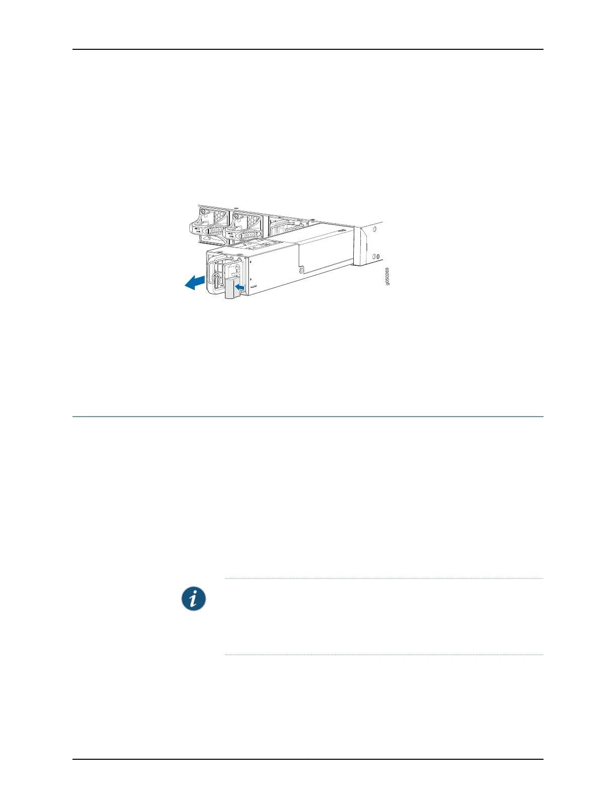
7. Place one hand under the power supply to support it and slide it completely out of
the chassis. Take care not to touch power supply components, pins, leads, or solder
connections.
8. Place the power supply in the antistatic bag or on the antistatic mat placed on a flat,
stable surface.
Figure 31: Removing a Power Supply from an EX4600 Switch
Related
Documentation
AC Power Supply in an EX4600 Switch on page 23•
• Connecting AC Power to an EX4600 Switch on page 147
• Connecting DC Power to an EX4600 Switch on page 149
• Installing a Power Supply in an EX4600 Switch on page 168
Installing an Expansion Module in an EX4600 Switch
The EX4600 switch allows up to two expansion modules to be added to the port panel
to increase port density. The EX4600 switch holds two bays of expansion modules that
can be mixed and matched as desired. The supported modules are:
•
QFX-EM-4Q–Each module adds four Quad Enhanced Small Form-Factor Pluggable
(QSFP+) ports
•
EX4600-EM-8S–Each module adds eight 10 Gigabit RJ-45 ports
Both the QFX-EM-4Q and the EX4600-EM-8S are hot-removable and hot-insertable
field-replaceable units (FRUs). You can remove and replace these modules without
powering off the switch or disrupting switch functions.
NOTE: When an expansion module is installed in the switch or an existing
expansion module is replaced with another expansion module, the switch
detects the ports on the expansion module. The switch creates the required
interfaces when transceivers are installed in these ports.
Before you begin installing an expansionmodulein the switch,ensure that you have taken
the necessary precautions to prevent electrostatic discharge (ESD) damage (see
“Prevention of Electrostatic Discharge Damage” on page 120).
Ensure that you have the following parts and tools available:
171Copyright © 2014, Juniper Networks, Inc.
Chapter 20: Replacing Components