NOTE: The fan module provides FRU-to-port or port-to-FRU airflow
depending on the switch product SKU you purchase. In legacy switches, or
switches with an LCD, this airflow is called front to back and back to front.
Before you install a fan module in an EX4600 switch, ensure that you have taken the
necessary precautions to prevent electrostatic discharge (ESD) damage (see “Prevention
of Electrostatic Discharge Damage” on page 120).
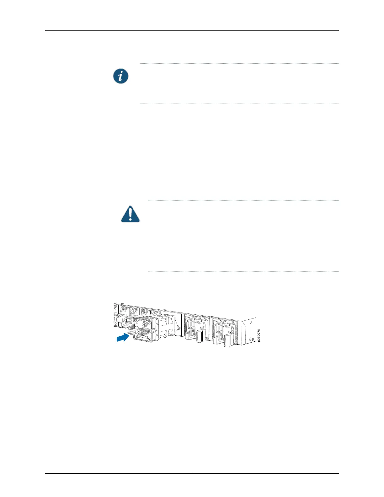
To install a fan module in an EX4600 switch (see Figure 34 on page 175 ):
1. Attach the ESD grounding strap to your bare wrist, and connect the strap to the ESD
point on the chassis.
2. Taking care not to touch the connectors, remove the fan module from its bag.
3. Align the module with the open slot on the management panel of the chassis and
slide it in until it is fully seated.
CAUTION: Damage can occur if you attempt to install a fan module into
a chassis with a different airflow direction. Compare the switch product
SKU with the airflowmarking on the handle to ensure that youare installing
a fan module with the same airflow direction as the chassis. The fan
modules are designed so that they can only be inserted into the EX4600
switch product SKU that supports the same airflow type. See “Cooling
System and Airflowin an EX4600 Switch” on page13 formore information.
4. Using a Phillips screwdriver, turn the locking screw until it is tight.
Figure 34: Installing a Fan Module in an EX4600 Switch
Q
F
X5100-48S
RUNNING JUN OS
Related
Documentation
Removing a Fan Module from an EX4600 Switch on page 176•
• Cooling System and Airflow in an EX4600 Switch on page 13
• Field-Replaceable Units in an EX4600 Switch on page 6
• Management Panel of an EX4600 Switch on page 9
175Copyright © 2014, Juniper Networks, Inc.
Chapter 20: Replacing Components