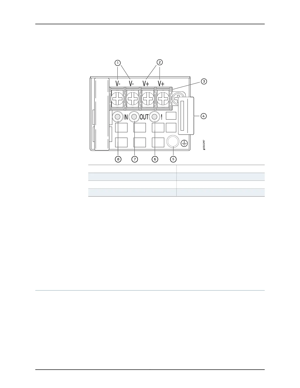
Figure 14: DC Power Supply Faceplate in EX4600 Switches
5—1— ESD grounding pointFeed B input terminals
6—2— Fault LEDFeed A input terminals
7—3— Output LEDTerminal block
8—4— Input LEDEjector lever
To avoid electrical injury, carefully follow instructions in “Installing a Power Supply in an
EX4600 Switch” on page 168 and “Removing a Power Supply from an EX4600 Switch”
on page 169.
Related
Documentation
DC Power Supply LEDs on an EX4600 Switch on page 195•
• Management Panel of an EX4600 Switch on page 9
• Field-Replaceable Units in an EX4600 Switch on page 6
• DC Power Specifications for an EX4600 Switch on page 81
• Prevention of Electrostatic Discharge Damage on page 120
• Connecting DC Power to an EX4600 Switch on page 149
Grounding Cable and Lug Specifications for an EX4600 Switch
For installations that require a separate grounding conductor to the chassis, the switch
must be adequately grounded before power is connected to ensure proper operation
and to meet safety and electromagnetic interference (EMI) requirements. To ground an
EX4600 switch, connect a grounding cable to earth ground and then attach it to the
chassis grounding points.
Copyright © 2014, Juniper Networks, Inc.26
EX4600 Switch Hardware Guide