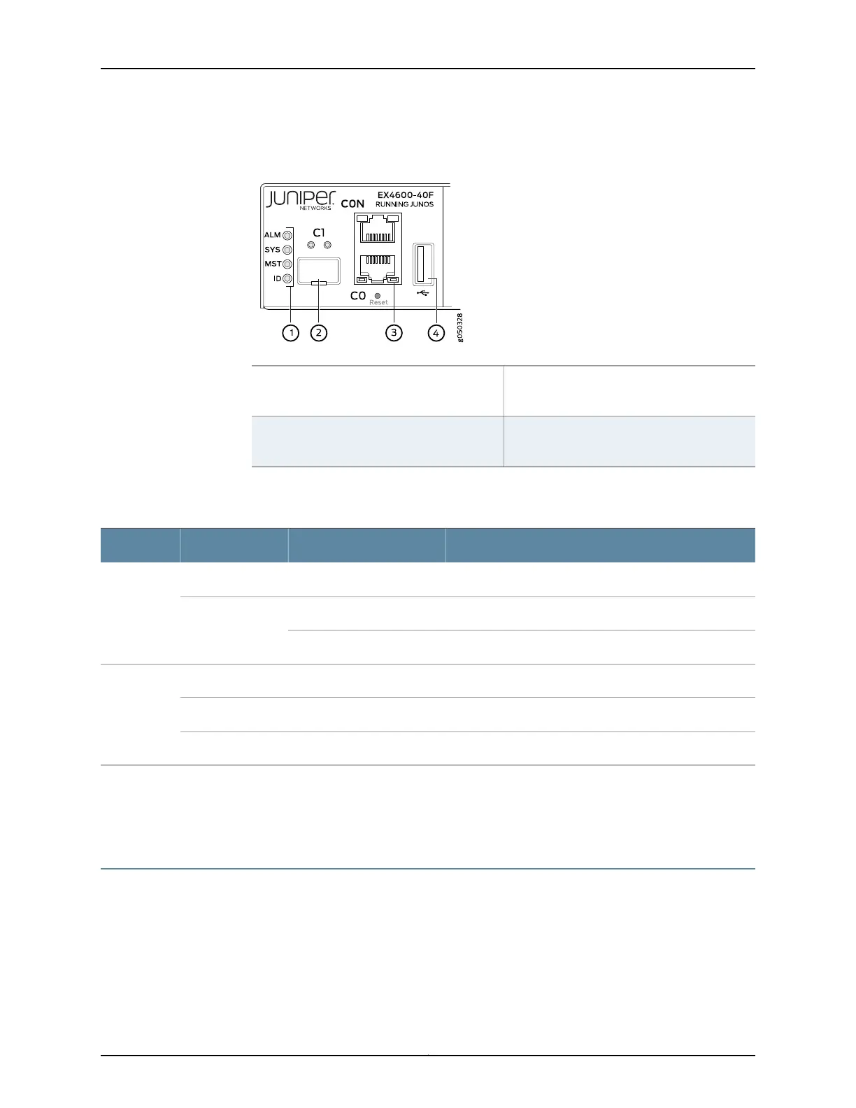
Figure 40: Management Port LEDs on an EX4600 Switch
3—1— em0–RJ-45 (10/100/1000 Base-T)
managementEthernetport (C0).The RJ-45
console port (CON) is above C0.
Status LEDs
4—2— USB portem1–SFP management Ethernet port (C1)
Cage (socketfor either 10/100/1000 Base-T
RJ45 SFP or 1GbE fiber SFP)
Table 37 on page 191 describes the management port LEDs.
Table 37: Management Port LEDs on an EX4600 Switch
DescriptionStateColorLED
No link is established, there is a fault, or the link is down.OffUnlitLink/Activity
A link is established, but there is no link activity.On steadilyGreen
A link is established, and there is link activity.Blinking or flickering
Either the port speed is 10 M or the link is down.OffUnlitStatus
The port speed is 1000 M.On steadilyGreen
The port speed is 100 M.On steadilyAmber
Related
Documentation
Management Panel of an EX4600 Switch on page 9•
• Connecting an EX4600 Switch to a Network for Out-of-Band Management on page 155
Access Port and Uplink Port LEDs on an EX4600 Switch
The Link/Activity and Status LED configuration for an EX4600 switch uses bi-colored
LEDs. The two figures in this topic show the location of those LEDs:
191Copyright © 2014, Juniper Networks, Inc.
Chapter 23: Viewing System Information