8.8 Setting input and output signals
The controller's analogue and digital inputs and outputs can be used for customised messages
and/or other functions.
The various options are explained in the following chapters:
■ 8.8.1: Output operational states of machine on digital outputs
■ 8.8.2: Output input signals on the display
■ 8.8.3: Switching and/or triggering messages with thresholds
The controller only allows assignment of spare inputs and outputs.
Any assignment of a pre-assigned input or output is discarded by the controller.
Spare outputs can be found in the machine circuit diagram.
➤ Set the inputs and outputs as described below.
8.8.1 Output operational states of machine on digital outputs
Important operational machine states can be made available as digital signals via floating contacts.
Each output can be assigned only once.
The following messages can be output:
Message Explanation Output
Controller on Controller is powered up
ON LOAD The machine is running in LOAD mode
Collective error Fault has occurred
Collective warning Warning message has appeared
Tab. 79 Assigned output signals
8.8.1.1 DO-functions menu
The requested message can be assigned to a free digital output (DOR orDOT).
Precondition Access level 2 is activated.
1. Open the 5.10.1
<Configuration – I/O periphery – DO-functions>
menu.
A menu containing a list of available messages and their assigned outputs is displayed.
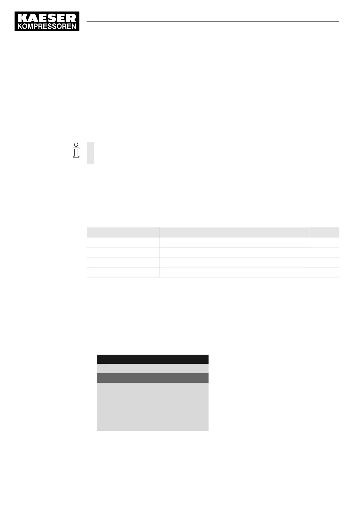
4 0 0 m b a r 0 8 : 1 5 A M 8 0 ° C
Header
5.10.1 DO-functions
Menu
On load
Active line
DOR1.05 ☐ ¦ Logic : +
······························
Controller on
DOR1.03 ☐ ¦ Logic : +
······························
8.8.1.2 Assigning a message to an output
1. Select the required message with the «Up» or «Down» keys.
8 Initial Start-up
8.8 Setting input and output signals
120
Service Manual Controller
SIGMA CONTROL 2 BLOWER ≥ 2.5.3 No.: 901700 10 E

 Loading...