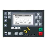
1. For displays on the communication module, see chapter 9.
Please contact KAESER Service if one or both of the LEDs are lit up or flash red.
2. Displays in the
<Communication – Com-Module>
menu.
In the 8.2
<Communication – Com-Module>
menu, communication faults are displayed as text
beneath the line
Status
or as a number after the term
Error
.
No.: Fault text Possible cause Measure
1 COM Module fault Defective module. Call KAESER SERVICE.
2 Communication
error
Bus coupling via commu‐
nication module is inter‐
rupted.
Check bus conduits and plug.
Incorrect slave address of
the module.
Set the slave address at the
SIGMA CONTROL 2 as parametrised at
the bus master.
3 Firmware error Defective module. Call KAESER SERVICE.
4 COM Module
deactivated
Module is not activated. Start the communication, see chapter 8.
5 COM Module not
identified
No KAESER communica‐
tion module.
Use only original KAESER communication
module.
90 Error Bus
monitoring
Bus master does not re‐
turn the toggle bit within
the monitoring interval.
■ Check the software of the bus master.
Check the time-out time, see chapter
8.
■ Deactivate monitoring if it has been ac‐
tivated inadvertently. See chapter 8.
Tab. 99 Fault displays in the Communication – Com-Module menu.
Result The bus communication is automatically continued as soon as the cause of the fault is remedied.
10.7.2 Troubleshooting at the Modbus module
10.7.2.1 Machine and SIGMA CONTROL 2
In the event of a fault in the bus communication, the red "Communication" and the yellow "Warn‐
ing" LEDs flash at the SIGMA CONTROL 2. The system displays the following warning message:
Message Possible cause Measure
0015 W Com-Module
communication error
Bus coupling via communication module
is interrupted.
Check bus lines and plug.
Incorrect or faulty communication mod‐
ule
Check communication
module, see below.
Tab. 100 Com-Module communication error warning message
In addition to the
0015 W Com-Module communication error
warning message, the system dis‐
plays the following information for troubleshooting:
1. See chapter 9 for display on the communication module.
If one or both LEDs are illuminated red or blink red, contact KAESER SERVICE.
10 Fault Recognition and Rectification
10.7 Communication modules
No.: 901700 10 E
Service Manual Controller
SIGMA CONTROL 2 BLOWER ≥ 2.5.3
163

 Loading...