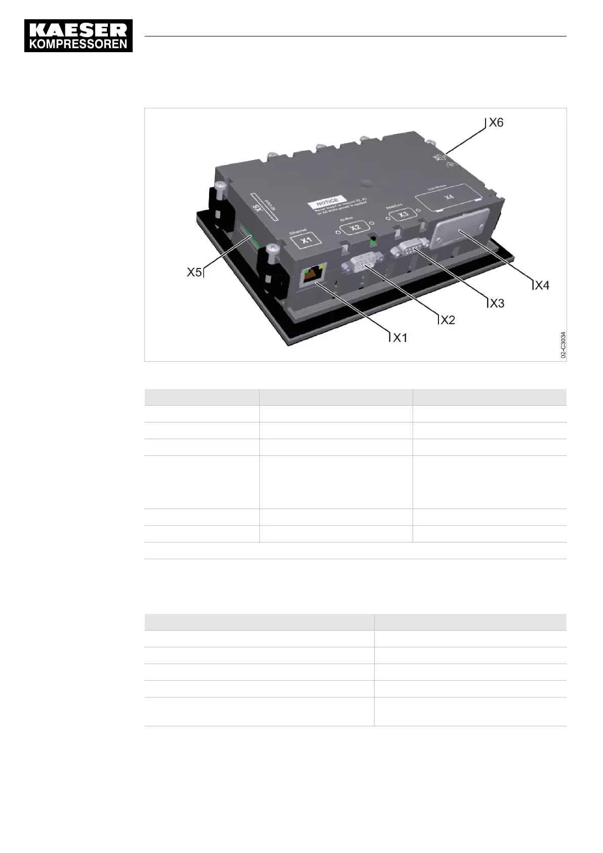
Fig. 3 MCS interfaces
Identification Interface Connection
X1 Ethernet 10/100 Base T RJ 45 socket
X2 I/O bus 9-pole SUB-D pins
X3 RS485–FC (USS interface) 9-pole SUB-D socket
X4 Com modules,
slot for communications module
Module optional for:
PROFIBUS, PROFINET,
Modbus RTU, Modbus TCP,
DeviceNet, EtherNet/IP
X5 SD card, SD card slot SD/SDHC card
X6 FE Functional earth (FE)
The positions of the interfaces X1–X6 are marked on the rear of the controller.
Tab. 10 MCS interfaces
Identification with RFID Equipment Card
Characteristic Value
Hardware on the SIGMA CONTROL 2 controller RFID reader
Hardware (external) RFID Equipment Card
Recognition distance [m] Max. 0.05
Frequency [MHz] 13.56
Emitted maximum transmitting power at 10 m dis‐
tance [dB(µA/m)]
11
Tab. 11 RFID
3 Technical Specifications
3.1 Controller SIGMA CONTROL 2
10
Service Manual Controller
SIGMA CONTROL 2 BLOWER ≥ 2.5.3 No.: 901700 10 E

 Loading...