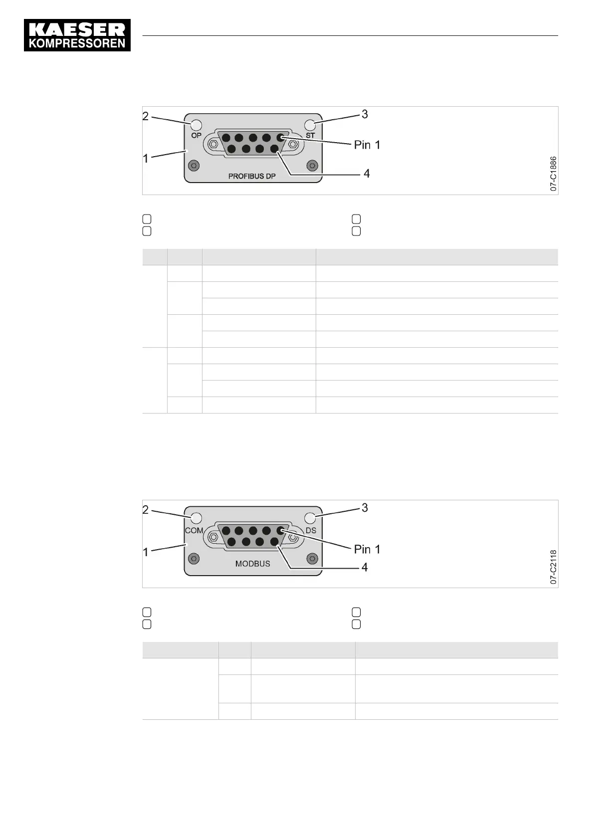
Fig. 36 PROFIBUS communication module – LEDs and interface
1 PROFIBUS communication module
2 LED OP: Operating mode
3 LED ST: Status
4 Sub-D port, 9 poles
LED Colour State Meaning
OP off Module without voltage/not connected to bus
Green flashes Module connected to bus
illuminates continuously Module connected to bus, communication is running
Red flashes 1:1 (on:off) Parametrisation error
flashes 2:1 (on:off) PROFIBUS configuration error
ST off Module without voltage/deactivated
Green illuminates continuously Module in operation
flashes Module in operation, internal diagnosis available
Red illuminates continuously Error
Tab. 88 PROFIBUS communication module – Interpretation of LEDs
9.8.2 Display at the Modbus module
The communication module features LEDs providing information about the module status.
Fig. 37 Modbus communication module – LEDs and interface
1 Communications module
2 LED Common rail system: Communication
3 LED DS: Device Status
4 Sub-D port, 9 poles
LED Colour State Meaning
Common rail
system
off Module without voltage or no communication
Yellow illuminates continuously Module connected to bus, communication is
running
Red illuminates continuously Error
9 Operation
9.8 Communication modules
144
Service Manual Controller
SIGMA CONTROL 2 BLOWER ≥ 2.5.3 No.: 901700 10 E
 Loading...
