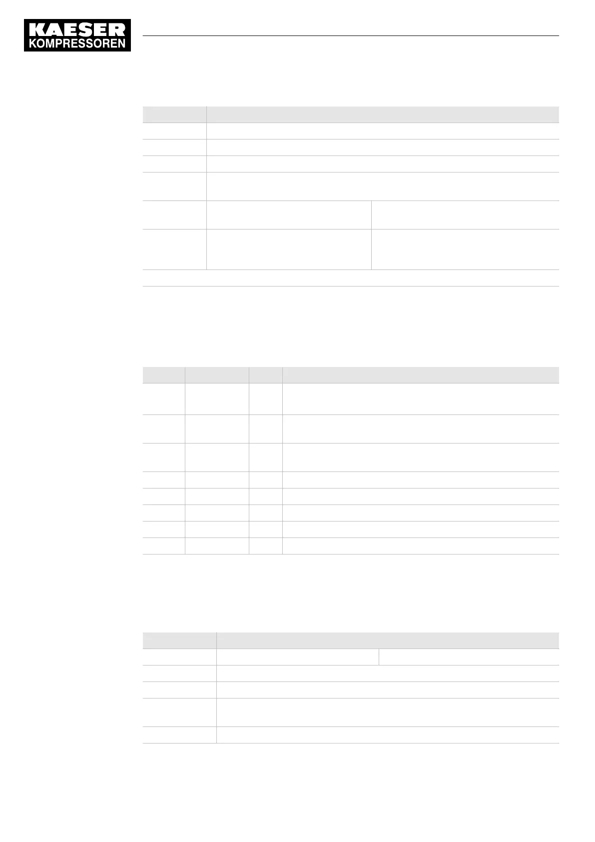
Feature Value
Time-out [ms] Possible settings 0...2000 ... 99999
Data bits: RTU: 8, ASCII: 7
Mode Possible settings RTU / ASCII
Input data
[byte]
64
Output data
[byte]
128 (process data) and 42 (diagnos‐
tic data)
128 (prozess data)
Data content "Technical description
SIGMA CONTROL 2 process image",
document number 7_7601xPA.
"Technical description
SIGMA AIR MANAGER 4.0 process im‐
age", document number 7_9696_PA.
Bold elements: Factory setting
Tab. 21 Technical Specifications - SIGMA CONTROL 2 interface
Assignment of the SIGMA CONTROL 2 interface
The Modbus interface is galvanically isolated and features RS485 and RS2232 signals. To use the
RS232 interface, connect Pin 2 with Pin 3.
Pin Direction Signal Description
1 — GND
C/C’
Data reference potential (isolated),
RS485: Bus polarisation, for terminating resistor (pull-down)
2 Output VP +5V DC (isolated, max. 10mA) RS485: Bus polarisation,
+5V for terminating resistor (pull-up)
3 Input PMC To use RS232, connect with Pin 2.
To use RS485, keep open.
5 Bi-directional B/B’ RS485 B (RxD/TxD positive)
7 Input RxD RS232 Receive data
8 Output TxD RS232 Send data
9 Bi-directional A/A’ RS485 A (RxD/TxD negative)
Housing — — Internally connected to functional earthing (FE)
Tab. 22 Assignment of the SIGMA CONTROL 2 interface
3.2.3 Modbus TCP module
Modbus TCP-Interface
Feature Value
Controller SIGMA CONTROL 2 SIGMA AIR MANAGER 4.0
Bus Modbus TCP server (Slave)
Connection 2x RJ45 ports (Cat5e, shielded), integrated 2-port switch, potential isolation
Baud
rate [Mbit/s]
10/100, full duplex or half duplex
Input data [byte] 64
3 Technical Specifications
3.2 Communication modules
14
Service Manual Controller
SIGMA CONTROL 2 BLOWER ≥ 2.5.3 No.: 901700 10 E

 Loading...